How to Commission HVAC Fans Properly (TAB + Performance Verification)
- nexoradesign.net
- Apr 5
- 20 min read
Introduction: Why Fan Commissioning Is Where Good HVAC Design Succeeds or Fails
In many projects, the fan is treated as if its job is simple: install it, energize it, check rotation, and move on. That mindset is one of the most expensive habits in HVAC delivery. A fan can be perfectly selected on paper, properly procured, physically installed, and still fail the building operationally. The consequences show up everywhere: hot and cold complaints, poor ventilation, excessive noise, unstable pressurization, VAV box failures, dirty filter alarms too early, higher energy bills, and endless arguments between contractor, TAB agency, consultant, and operator.
This is why proper commissioning of HVAC fans is not a minor closeout activity. It is the point where design intent is translated into measurable system performance. It is where airflow, pressure, power, controllability, and actual field conditions are reconciled. In premium commercial, healthcare, hospitality, industrial, and high-rise projects, fan commissioning is not just about proving that equipment runs. It is about proving that the system delivers the required air quantity, against the actual installed resistance, with acceptable stability, efficiency, noise, and control response.
Too many projects confuse startup with commissioning. Startup proves the fan can operate mechanically and electrically without immediate damage. Commissioning proves the airside system performs as intended in service. TAB proves the air quantities are measured, adjusted, and documented. Performance verification proves the measured operating point is reasonable when compared against fan curves, system expectations, and design tolerances. All three are related, but they are not the same activity.
A properly commissioned fan system should answer several professional questions clearly:
Does the fan deliver the required airflow in the installed system?
Is the measured external static pressure consistent with the selected duty point?
Is the motor current, shaft power, or VFD loading acceptable?
Are dampers, VAV boxes, coils, filters, sound attenuators, and terminal devices behaving in a stable manner?
Is the system balanced at design, partial load, and control reset conditions?
Can the owner operate the system confidently without fighting instability, noise, or excessive energy use?
When these questions are ignored, the financial consequences are real. An undersupplied ventilation system can trigger IAQ complaints and regulatory exposure. An oversized fan with poor control can run far from its efficient point for years. A fan commissioned with dirty filters, closed dampers, poor straight lengths, or wrong sensor calibration may be “accepted” on paper and remain operationally defective for the life of the building.
This article is written for MEP engineers, consultants, developers, and senior project professionals who need consulting-level clarity on how HVAC fans should actually be commissioned in the field. It focuses on practical execution, not generic textbook summaries. The discussion covers TAB, performance verification, field measurement logic, engineering judgment, typical failure modes, and the financial impact of getting the process wrong.
The goal is simple: move from checkbox commissioning to defensible, high-quality fan performance verification. (How to Commission HVAC Fans Properly)
Related topics :
Fundamentals: What Fan Commissioning Actually Means
Startup, TAB, and Commissioning Are Not the Same
A recurring source of confusion on projects is the misuse of terms.
Startup is usually the manufacturer or contractor activity that confirms the equipment is electrically safe and mechanically operable. It covers checks such as rotation, bearing condition, lubrication where applicable, belt tension, motor protection settings, basic VFD configuration, and absence of abnormal vibration.
TAB stands for Testing, Adjusting, and Balancing. This is the disciplined field process of measuring actual airflow and pressure conditions, then adjusting dampers, fan speeds, and system settings so the design air quantities are achieved across the network.
Commissioning is broader. It verifies that the HVAC fan system, as integrated with controls and the rest of the airside plant, meets the owner’s project requirements and design intent. It includes functional testing, control sequence verification, stability checks, alarm verification, and documentation.
A fan can pass startup and still fail commissioning. A fan can also achieve nominal TAB airflow but still fail performance verification if the operating point is unstable, noisy, or energy-wasteful.
The Real Duty of an HVAC Fan (How to Commission HVAC Fans Properly)
An HVAC fan exists to overcome system resistance and move a required airflow. In practice, the installed duty point is determined by the intersection of the fan curve and the system curve. That operating point may differ from the scheduled design point for many reasons:
Actual duct pressure drop differs from estimate
Filters are dirtier or of different grade
Dampers are partly closed
Flexible duct is excessive
Sound attenuators create more drop than assumed
Coil pressure loss differs from submittal
Poor transitions increase system effect
VAV diversity assumptions are not matching reality
Field speed setting differs from design
Air density differs from the assumed rating point
Commissioning therefore requires more than measuring a few terminal flows. It requires understanding whether the measured system behavior makes engineering sense.
Core Performance Parameters That Must Be Verified
For most HVAC fans, the commissioning engineer or TAB professional should verify at least the following:
Airflow rate, typically in m³/s or L/s
Static pressure, usually Pa
Total pressure where relevant
Fan speed, rpm
Motor current, A
Input power, kW where possible
VFD frequency, Hz
Noise and vibration observations
Control stability and response
Filter condition and pressure drop
Damper positions and system balance state
These parameters are not independent. They influence each other. A fan delivering more airflow than design will usually see higher power draw and potentially more noise. A fan delivering less airflow than required may indicate system resistance is higher than expected or the fan speed is too low. A system that balances only with heavily closed dampers may reveal oversizing or poor design distribution.
Why TAB Is Central to Fan Commissioning
TAB is the bridge between fan-level performance and space-level outcomes. Even if a fan seems to produce adequate total airflow, the building may still fail if the distribution is poor. Proper TAB ensures the fan system is not judged only by aggregate flow, but by how that air is delivered.
For example, a supply fan may produce 10.0 m³/s against expected static pressure, but if major trunk branches are starved and downstream VAV boxes are near full open, the building will still underperform. Likewise, an exhaust fan may appear operational, but if branch capture is weak in toilets, kitchens, or process areas, the actual ventilation objective is not met.
Fan commissioning without TAB is incomplete. TAB without performance verification is shallow. Both are required.
Theory in Practical Terms: What Must Be Understood Before You Verify Anything
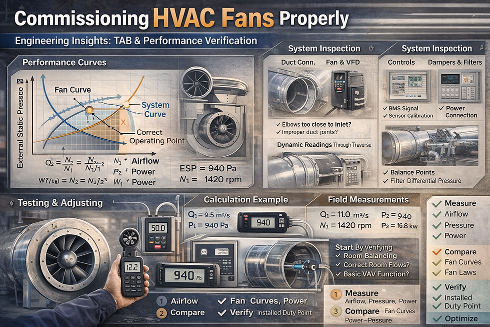
Fan Laws and Their Field Relevance
Fan laws are not academic decoration; they are essential for field interpretation.
For geometrically similar conditions:
Airflow is proportional to speed
Q2/Q1=N2/N1
Pressure is proportional to speed squared
P2/P1=(N2/N1)2
Power is proportional to speed cubed
W2/W1=(N2/N1)^3
Where:
Q = airflow
N = rotational speed
P = pressure
W = power
These relationships are extremely useful during commissioning. If a supply fan is short by 10% airflow and the system remains stable, a modest speed increase may correct it. But the power impact is not modest in the same proportion. A 10% speed increase can increase power by roughly 33%. That is why performance correction must always be checked against motor margin, VFD capacity, sound limits, and future dirty-filter operation.
System Curve Reality
The system curve typically behaves approximately with the square of airflow:
ΔP ∝ Q^2
That means small airflow increases may demand disproportionately higher pressure. This is why “just increase the speed a bit” can become a serious energy and noise penalty in real projects.
When field conditions differ from design, the system curve often shifts. For example:
More restrictive filters shift the system curve upward
Opened bypasses or missing components may shift it downward
Poor transitions or obstructions create extra local losses
Dirty coils increase resistance
Excess balancing damper throttling changes branch behavior
A commissioning team should therefore avoid assuming the original design pressure estimate is automatically correct. The installed system must be measured.
Air Density Correction Matters More Than Many Teams Admit
Fan performance depends on air density. If the manufacturer’s rating is based on standard air but the actual field condition differs materially, direct comparison without correction can mislead the team.
Standard density is often taken near 1.2 kg/m³ depending on reference condition. In hot climates, altitude variation, or unusual process systems, actual density may differ enough to affect fan pressure and power interpretation.
For most standard comfort applications at low altitude, the effect may not change acceptance drastically, but for high-accuracy verification or large systems, it should not be ignored.
System Effect Is a Commissioning Issue, Not Just a Design Issue
System effect occurs when the fan inlet or outlet conditions are disturbed by poor approach geometry: elbows too close to fan inlet, abrupt transitions, non-uniform velocity profiles, spin, swirl, and inadequate straight length. In the field, this often appears as:
Lower airflow than expected
Unstable measurement
Higher sound
Vibration
Operating point mismatch versus manufacturer selection
A project team may blame the fan manufacturer or TAB readings, when the real issue is poor duct arrangement near the fan.
This is exactly why commissioning must include a physical installation review, not just instrument readings.
Pre-Commissioning Requirements: What Must Be Ready Before TAB Starts
Documentation Must Be Reviewed First
No serious fan commissioning should begin before the team reviews:
Approved shop drawings
Fan selection data and curves
Motor and VFD details
Design airflow schedule
Design static pressure schedule
Filter pressure drop assumptions
Coil and accessory pressure drops
Control sequence
BMS points list
Balancing dampers and terminal schedules
Equipment startup reports
IOM manuals
Without this, field numbers become isolated data with no engineering context.
Construction Readiness Is Essential
A fan cannot be properly commissioned if the system is incomplete. The following should generally be ready:
Ductwork completed and sealed
Access doors installed
Filters installed and reasonably clean
Coils clean and free from construction debris
Fire and volume dampers open and functional
Ceiling work sufficiently complete
Terminal devices installed
VAV boxes commissioned to basic control readiness
Control sensors calibrated
BMS available where relevant
Permanent power established
VFDs fully configured
All intended branches connected
Trying to TAB a system before these conditions are met only produces unreliable numbers and repeated rework.
Cleanliness and Condition Matter
One of the most common field distortions is testing under non-representative conditions.
Examples include:
Filters missing during TAB
Access panels left open
Temporary construction openings in duct
Dirty coils during final testing
Temporary dampers or blank-offs not yet removed
Fan belts slipping
Incorrect pulley settings
Construction dust loading filters abnormally
A commissioning engineer must confirm the system condition reflects the intended operational state.
Related topics :
Detailed Technical Procedure: How to Commission HVAC Fans Properly
Step 1: Physical Installation Inspection
Before taking performance readings, inspect the fan installation physically.
Check the Fan Arrangement
Confirm the installed equipment matches the approved submittal:
Correct fan type
Correct model
Correct wheel orientation
Correct motor size
Correct drive arrangement
Correct VFD if applicable
Correct inlet/outlet connection orientation
Even experienced teams occasionally discover wrong pulley size, wrong wheel width, or wrong motor speed class after weeks of troubleshooting.
Inspect Duct Connections and System Effect Risks
Look for:
Elbows too close to inlet
Abrupt transitions
Flexible connectors collapsed or twisted
Eccentric transitions installed incorrectly
Obstructions at inlet screens
Discharge immediately into fittings without stabilization
Poorly supported duct causing distortion
These issues must be documented early because they can invalidate performance expectations.
Mechanical Condition Checks
Verify:
Rotation direction
Belt alignment and tension
Bearing condition
Lubrication status where relevant
Isolation mounts and springs
Vibration isolator snubbers released if required
Anchor points correct
No rubbing or wheel contact
Guards in place
A fan that is mechanically distressed should not be pushed into performance verification until corrected.
Step 2: Electrical and Controls Readiness Verification
Confirm the electrical basis of the test is reliable.
Electrical Checks
Verify:
Rated voltage available
Phase balance acceptable
Motor nameplate current and service factor known
Overload settings correctly adjusted
VFD parameters correct
Min/max speeds aligned with design
Control safeties operational
Interlocks functioning
Controls Checks
Confirm:
Start/stop command works
Status feedback works
Speed command range correct
Differential pressure sensors calibrated
Airflow proving works if used
Alarms for fan trip and filter dirty are operational
Static pressure reset sequence understood
Smoke/fire interfacing tested as applicable
A major source of commissioning failure is chasing airflow problems that are actually caused by incorrect control scaling or sensor offset.
Step 3: Establish Baseline Operating Conditions
Before full TAB, establish baseline fan performance.
Measure and record:
Fan speed
VFD output frequency
Suction/discharge static pressures where applicable
External static pressure
Motor current
Voltage
Approximate airflow if possible
Filter pressure drop
Coil pressure drop where measurable
Noise/vibration observations
This initial snapshot helps the team see whether the system is fundamentally close to expectation or obviously off.
Step 4: Measure Fan Airflow Properly
Measuring actual fan airflow is often harder than people assume.
Acceptable Field Methods
Depending on the system and available straight length, airflow may be measured by:
Pitot traverse in duct
Flow hood summation at terminals
Inlet cone measurement
Fan array measurement through station instruments
Airflow station via calibrated sensors
Nozzle or test port methods from manufacturer setup
Each method has strengths and limitations.
Pitot traverse is highly defensible if straight lengths are adequate and the technician is competent.
Flow hood summation may work for supply systems where terminal access is available and leakage is not excessive, but it can accumulate error over many terminals.
Airflow stations are useful but must be validated; some are poorly installed or uncalibrated.
Common Measurement Errors
Do not trust airflow numbers blindly if:
Traverse is too close to elbows, dampers, or transitions
Duct geometry is irregular
Terminal devices are not fully installed
Hood is used incorrectly on swirl diffusers
Leakage is significant
Return paths are incomplete
Fan arrays are operating unevenly
A professional commissioning report should state the measurement method and limitations.
Step 5: Verify Static Pressure Against the System Condition
Static pressure is often misunderstood. The question is not whether the fan produces “a lot of pressure,” but whether the measured pressure is consistent with the required airflow through the installed system.
External Static Pressure
For many AHUs and packaged systems, external static pressure is a key metric. It generally excludes internal equipment losses already accounted within the unit rating, depending on manufacturer convention. Teams must be clear on the definition used.
Measure pressure at appropriate tapping points. Poor pressure port location can distort results significantly.
Interpreting Pressure Readings
If airflow is low and pressure is high, the system may be too restrictive.
If airflow is high and pressure is low, the system may be less restrictive than assumed, or some branches may be too open.
If both airflow and pressure are low, speed may be too low or the measurement may be flawed.
If both airflow and pressure are high, the fan may be over speeding or system configuration differs from design.
This is where engineering judgment matters. Raw readings alone are not enough.
Step 6: Execute TAB Properly
Once baseline conditions are acceptable, proceed with systematic balancing.
General TAB Logic
For supply systems:
Confirm fan is stable at a provisional speed
Open all balancing dampers to initial positions as required
Confirm terminal devices accessible and installed
Measure branch and terminal flows
Adjust branch dampers progressively
Recheck total flow
Correct fan speed as needed
Repeat until overall system and terminals are within tolerance
For exhaust systems:
Confirm required extraction points are complete
Measure key branches and terminals
Adjust for intended capture or extract rates
Verify room pressure relationships where applicable
Reconfirm fan total airflow and static pressure
Tolerances
Exact tolerances depend on project specification, standards, and system type. Typical acceptance logic may include terminal and branch deviations within specified percentages, with total system airflow aligned with design target. The key is consistency with the contract requirement. The commissioner should not improvise tolerances late in the job.
Interaction with VAV and Controls
On variable air volume systems, TAB must distinguish between:
Maximum design flow
Minimum flow
Diversity operation
Static pressure reset behavior
Balancing a VAV system at one unstable control condition is not proper commissioning. The fan should be proven under conditions relevant to design intent, including control transitions.
Related topics :
Step 7: Verify Motor Load and Energy Implications
After airflow and pressure are stabilized, check motor and VFD loading.
Electrical Verification
Measure:
Current on all phases
Voltage
Power factor if available
Input kW from VFD/BMS or portable analyzer
Compare against motor FLA and expected absorbed power
A fan that meets airflow but operates near motor overload is not acceptably commissioned.
Example Power Check
Suppose a supply fan delivers 8.5 m³/s at 780 Pa total pressure. Assume overall fan-motor-drive efficiency of 62%.
Air power:
Pair = Q×ΔP = 8.5×780 = 6630 W = 6.63 kW
Electrical input power:
Pinput = 6.63/0.62 = 10.69 kW
If field measurement shows 13.2 kW, the team should ask why. Possible reasons:
Efficiency lower than assumed
Airflow or pressure measurement error
Mechanical losses
Dirty system
Operating point off the selected efficient region
Motor or VFD inefficiency higher than expected
This is how performance verification becomes meaningful. It is not just recording numbers; it is checking whether the numbers are coherent.
Step 8: Functional Performance Verification
After TAB, the system should be functionally tested.
Verify Control Sequence
Test the fan under realistic operating scenarios:
Occupied start
Unoccupied shutdown
Fire mode as applicable
Static pressure reset response
Filter alarm response
VFD fault alarm
Standby fan changeover if duty/standby arrangement exists
Fan array lead-lag behavior if applicable
Observe Stability
A properly commissioned fan should not hunt excessively. Static pressure should stabilize, not oscillate continuously because of bad PID tuning, poor sensor location, or improper minimum speed.
Check Partial Load Conditions
Many systems appear acceptable at full design flow but waste large amounts of energy at partial load. Verify whether the fan turns down smoothly and whether distribution remains acceptable in reduced-flow operation.
Step 9: Final Reporting and Acceptance
A defensible commissioning report should include:
Fan identification and location
Design duty
Measured duty
Measurement method
Fan speed
Static pressure readings
Airflow readings
Motor current and power
Control sequence observations
Outstanding issues
Corrective actions taken
Final acceptance status
Limitations or caveats
Good commissioning documentation does not hide field complexity. It explains it.
Step-by-Step Calculation Methodology for Field Verification
To make this practical, below is a field-oriented methodology.
Step A: Determine Design Reference Values
Assume design supply fan duty:
Airflow = 10.0 m³/s
Static pressure = 900 Pa
Motor input expectation = 15 kW
Speed = 1450 rpm
Step B: Measure Actual Field Values
Measured after initial TAB:
Airflow = 9.1 m³/s
Static pressure = 1020 Pa
Speed = 1450 rpm
Input power = 14.8 kW
Interpretation: airflow is low, pressure is high. System resistance is likely higher than design.
Step C: Estimate Required Speed Correction
Using fan law:
Q2 / Q1 = N2 / N1
Required new speed:
N2 = 1450×(10.0/9.1) = 1593 rpm
This is about 9.9% increase in speed.
Step D: Estimate Pressure at New Speed
P2 = 1020×(1593/1450)^2
P2≈1020×1.207=1231 Pa
Step E: Estimate Power at New Speed
W2 = 14.8×(1593/1450)^3
W2 ≈ 14.8×1.327 = 19.64 kW
This reveals a problem immediately. The required speed correction may exceed the motor design margin. Therefore the right action is not blindly increasing speed. The team must identify why system resistance is too high:
Closed dampers?
Dirty filters?
Extra pressure drop in attenuator?
Poor duct installation?
Coil face blockage?
Incorrect pressure assumption in design?
System effect near the fan?
This is exactly why fan commissioning must be analytical, not procedural only.
Real Project Example: Office Tower Supply Fan Commissioning
Consider a medium-size office tower AHU serving one floor plate.
Design Intent
Supply airflow: 12.0 m³/s
ESP: 850 Pa
VAV system with pressure reset
F7 filters, chilled water coil, sound attenuator
Fan controlled by VFD
Initial Problem Observed
During partial occupancy, tenants reported warm perimeter zones and stuffy meeting rooms. The contractor claimed the fan was “running fine.” Startup report was clean. However, VAV boxes at the end of long branches were near 100% open most of the time.
Field Findings
Initial commissioning data:
VFD at 50 Hz
Measured total supply flow by traverse: 10.8 m³/s
Static pressure sensor near fan discharge reading 300 Pa
Downstream remote branch pressure checks indicated poor distribution
Filter differential pressure already high
Sound attenuator pressure drop higher than design due to internal lining damage and partial obstruction
Several branch dampers had been excessively throttled in easier zones during rushed preliminary balancing
Static pressure sensor location was too close to turbulent discharge zone
Corrective Actions
Replaced damaged attenuator section
Relocated static pressure sensor to a better representative main duct position
Reopened over-throttled dampers and rebalanced systematically
Cleaned temporary construction debris from return path and coil face
Rechecked fan speed and power after proper balancing
Final Results
Measured supply airflow: 11.95 m³/s
Stable static pressure reset achieved
Terminal flows within specification
Fan input power reduced from unstable 16.2 kW to 14.9 kW at comparable high-load state
Complaints reduced substantially within days
VAV damper positions normalized
Engineering Lesson
The original issue was not simply “fan too small.” It was a compound commissioning failure involving poor sensor location, obstructed attenuator, premature balancing, and non-representative control operation. Without proper TAB and performance verification, the likely response would have been increasing fan speed, which would have raised energy and noise while failing to solve the root cause fully.
Design Considerations and Engineering Judgment
Commissioning Starts at Design Stage
Many field commissioning problems are actually design-stage omissions. Designers should help successful commissioning by providing:
Clear design airflow and pressure schedules
Rational diversity assumptions
Straight duct lengths for measurement where possible
Proper sensor locations
Access doors for inspection and traversal
Realistic filter dirty allowances
Reasonable balancing strategy
Fan curves and selected operating points on submittals
Acceptance criteria in specification
Oversizing Is Not a Safe Strategy
Many teams still oversize fans thinking it reduces risk. In reality, oversizing often creates:
Excessive throttling
Poor controllability
Noise
Low efficiency at actual operating point
More difficult balancing
Higher capital cost
Higher life-cycle energy use
Good commissioning frequently reveals that oversized fans are harder to stabilize than correctly sized fans.
Allowance for Dirty Filters Must Be Intelligent
A fan should be evaluated in relation to both clean and design-dirty conditions. If the fan barely meets airflow only with clean filters, future operation will suffer. But sizing for excessively conservative dirty-filter pressure can also create chronic energy waste. The engineer must balance resilience and efficiency.
Measurement Limitations Must Be Acknowledged Honestly
Not every installed system offers ideal traverse locations. In such cases, the commissioner must use the best available method and state the uncertainty. Pretending to have precision where the geometry does not support it undermines the integrity of the process.
Cost, Energy, and ROI Impact of Proper Fan Commissioning
Energy Cost Impact
Fans are continuous or near-continuous energy users in many buildings. Even modest performance errors matter.
Suppose a fan is operating 2.5 kW above what is necessary because of poor commissioning and unnecessary overspeed.
Annual energy waste at 4,000 operating hours:
2.5×4000=10,000 kWh/year
At an electricity cost of 0.12 USD/kWh:
10,000×0.12=1,200 USD/year
That is for one fan only. In a commercial building with multiple AHUs, car park exhaust fans, stair pressurization units, and fresh air systems, the aggregate waste can become very substantial.
Soft Cost Impact
Poor fan commissioning also creates non-energy costs:
Occupant complaints
Repeat TAB visits
Consultant reinspection time
Contractor rework
Delayed handover
BMS retuning
Warranty disputes
Loss of developer reputation
These indirect costs often exceed the direct energy waste.
ROI of Proper Commissioning
The cost of competent TAB and performance verification is usually small relative to HVAC capital cost. If good commissioning prevents only one major rework loop or optimizes even a few fan systems, the payback is often immediate or within the first year.
For premium developments, proper commissioning is not a cost center. It is risk control.
Common Mistakes to Avoid
Treating Startup as Final Acceptance
This is perhaps the most common mistake. A rotating fan is not a commissioned fan.
Measuring Airflow in Bad Locations and Trusting the Number Anyway
A poor traverse location can create false confidence and bad decisions.
Balancing Before the System Is Complete
TAB done before filters, ceilings, terminals, or controls are ready often has to be repeated.
Ignoring System Effect
If inlet and outlet geometry are poor, the fan may never achieve the catalog expectation. This should be identified, not hidden.
Using Control Sensors That Are Poorly Located or Uncalibrated
A bad static sensor can make a good fan look bad, or a bad system look acceptable.
Adjusting Fan Speed Without Checking Motor and Power Margin
Correcting airflow blindly can create overload and long-term reliability problems.
Accepting a System That Meets Total Flow But Fails Distribution
Total airflow alone is not enough. Space-level delivery matters.
Excessive Damper Throttling to Force Balance
This often masks design or sizing issues and increases operating cost.
Failing to Verify Partial Load Performance
Modern HVAC systems spend much of their life away from peak design flow. Commissioning only at one full-load point is incomplete.
Poor Documentation
If the report does not explain method, readings, limitations, and corrections, future troubleshooting becomes much harder.
Optimization Strategies for Better Fan Commissioning Outcomes
Use Trending, Not Just Spot Readings
Where BMS exists, trend fan speed, static pressure, airflow station signal, filter DP, and VAV positions. This reveals problems that spot testing misses.
Compare Multiple Indicators
Do not rely on one metric only. A credible assessment combines airflow, pressure, power, damper position, and control behavior.
Optimize Sensor Placement
Remote main duct static pressure sensors often perform better than fan discharge locations, provided they are placed thoughtfully.
Revisit Damper Strategy After TAB
A system balanced with excessive throttling may be improved through selective resizing or reconfiguration in major projects.
Commission at More Than One Operating Point
For VAV systems, verify high flow, moderate flow, and reduced flow conditions.
Challenge the Original Assumptions When Necessary
Sometimes the field proves the design pressure estimate was wrong. Mature engineering accepts this and corrects the record rather than forcing the system into inefficient operation to preserve appearances.
Advanced Insights for Experienced Engineers
Use Power as a Reality Check
When airflow and pressure measurements seem inconsistent, motor input power can help identify likely error. While not sufficient on its own, it is a useful cross-check.
Watch VAV Damper Population Behavior
On VAV floors, distribution quality can often be inferred by the pattern of box positions. If many critical zones are near full open while the fan is already at high speed, the system may be under-delivering or poorly distributed. If many boxes are nearly shut while static remains high, the fan may be excessive or reset poorly tuned.
Consider Seasonal Re-Verification
Some systems behave differently after occupancy stabilizes, filters age, tenancy fit-out changes branch load patterns, or coils get dirtier. For major buildings, a post-occupancy seasonal review can be very valuable.
Fan Arrays Require Special Attention
Fan arrays add redundancy and control flexibility, but they also require verification of staging logic, equal loading, failed-fan response, and airflow stability across operating combinations.
Noise and Vibration Are Performance Indicators Too
A fan meeting airflow at the cost of objectionable noise, rumble, or structural vibration is not properly commissioned. Acoustic quality should be treated as part of performance verification, not as a separate afterthought.
FAQ
1. Is fan commissioning necessary if the manufacturer has already started up the fan?
Yes. Startup only confirms mechanical and electrical operability. It does not prove the installed airside system meets design airflow and control performance.
2. Can TAB be completed before ceilings and terminal devices are fully
installed?
It can be attempted provisionally, but final TAB should not be accepted until the system is substantially complete and representative of final operating condition.
3. What is the most reliable way to measure fan airflow?
It depends on field conditions. A properly executed duct traverse is often strong evidence, but airflow stations, inlet cones, or terminal summation may also be appropriate.
4. Why does a fan sometimes fail to meet airflow even though motor current is low?
Low current may indicate the fan is operating at a lower airflow and lower absorbed power than expected, often due to low speed or a shifted operating point.
5. Should dirty-filter condition be included during commissioning?
The system should at least be evaluated with awareness of clean versus dirty filter allowances. Final acceptance is often at clean or near-clean condition, but future margin should be understood.
6. How close should measured airflow be to design?
That depends on project specification and applicable standards. The correct reference is the contract requirement, not assumption.
7. Is high static pressure always a bad sign?
Not by itself. High pressure combined with low flow may indicate excessive resistance. Pressure must be interpreted together with airflow and system condition.
8. Why do some balanced systems still have comfort complaints?
Because total system airflow is not the same as proper distribution, control stability, or room pressure performance.
9. Can increasing VFD speed solve most commissioning issues?
No. It can sometimes recover airflow, but it can also increase energy, noise, and overload risk while hiding the real problem.
10. What is the role of the consultant during fan commissioning?
The consultant should verify design intent, review TAB methodology, interpret performance reasonableness, witness testing where appropriate, and ensure acceptance is technically defensible.
11. How important is sensor calibration in VAV fan commissioning?
Very important. A poorly calibrated or badly located static pressure sensor can destabilize the entire fan control sequence.
12. What are the biggest red flags during fan TAB?
Unstable readings, excessive throttling, poor branch distribution, overloaded motors, high noise, and large mismatch between expected and measured operating point.
13. Should return and exhaust fans be commissioned with the same rigor as supply fans?
Yes, especially where pressure relationships, ventilation compliance, smoke control support, or odor containment are important.
14. What documents should the owner request at handover?
Final TAB report, startup report, commissioning report, control sequence verification, as-built setpoints, and fan curve reference documentation.
15. When should a system be recommissioned?
After major tenant fit-out, filter strategy change, duct modification, recurring comfort issues, or persistent energy underperformance.
Strong Conclusion: Commissioning Fans Properly Is an Engineering and Financial Discipline
HVAC fan commissioning is not a ceremonial closeout step. It is one of the most important technical checkpoints in the delivery of an HVAC system. A fan is the moving force behind ventilation, pressurization, comfort delivery, heat transfer effectiveness, and often a meaningful portion of the building’s electrical consumption. If the fan system is not properly tested, adjusted, balanced, and verified, the project may look complete while remaining operationally compromised.
The professional approach is clear. First, confirm the installation is mechanically and electrically sound. Then measure what the fan is actually doing in the real installed system. Then perform proper TAB so the airflow is not only adequate in total, but correctly distributed. After that, verify pressure, speed, power, and control behavior against design intent and engineering reasonableness. Finally, document the result in a form that the owner, consultant, and operator can trust.
For consultants and developers, this is also a commercial issue. Proper fan commissioning reduces handover disputes, protects occupant experience, lowers energy waste, shortens defect periods, and improves building credibility. For contractors, it reduces painful rework loops. For operators, it provides a stable foundation for long-term maintenance and efficient operation.
The most expensive fan problem is rarely the fan itself. It is the accepted-but-unverified system around it.
When HVAC fans are commissioned properly, the result is not just compliance. It is a building that performs as intended, costs less to operate, and creates fewer surprises after occupancy. That is the standard serious projects should aim for.
Author’s Note
This article is provided for guidance only. Actual commissioning requirements, acceptance tolerances, testing methodology, and documentation format should always follow the project specification, applicable codes and standards, manufacturer recommendations, and the professional judgment of the responsible engineers and TAB specialists.


Comments