Fan Noise Control in HVAC Systems (Engineering + Acoustic Solutions)
- nexoradesign.net
- Apr 9
- 17 min read
Executive Overview
Fan noise control in HVAC systems is not a decorative add-on, and it is not a specialist issue that can be deferred until late-stage commissioning. It is a core engineering design responsibility that directly affects occupant comfort, asset value, tenant satisfaction, regulatory compliance, and the long-term credibility of the MEP design team. In many projects, HVAC systems meet airflow, cooling, heating, and pressurization requirements but still fail in operation because the acoustic outcome was not engineered with the same discipline as thermal and hydraulic performance.
The reason is simple: fan noise is generated by the same physical processes that make the system work. Pressure rise, blade passing, turbulence, flow separation, casing breakout, duct-borne transmission, vibration transfer, and terminal discharge behavior are all embedded in normal HVAC operation. When these mechanisms are not controlled at concept and design stage, the result is often a technically “functional” system that is acoustically unacceptable.
This is especially important in commercial offices, hotels, hospitals, schools, mosques, residential towers, mixed-use developments, and premium retail environments, where acoustic quality is directly tied to user perception of building quality. A system that is too noisy will trigger complaints even when all mechanical capacities are correct. In some buildings, noise complaints emerge before thermal complaints. Occupants may tolerate a minor temperature offset for a short period, but repetitive broadband rumble, tonal fan noise, discharge hiss, or low-frequency structure-borne vibration is perceived immediately and judged harshly.
From an engineering standpoint, fan noise control requires coordinated decisions across fan selection, airside pressure management, duct routing, equipment room planning, vibration isolation, attenuator sizing, terminal selection, architectural separation, and commissioning strategy. There is no single silencer or single rule that solves the problem. Good acoustic performance comes from reducing sound power at source, interrupting transmission paths, avoiding aerodynamic instability, and ensuring the receiving space criteria are achievable.
(Fan Noise Control in HVAC Systems)
A consulting-grade approach therefore asks the right questions early:
Read related topics :
Most Common Mistakes in Jet Fan Ventilation System Design and Installation
Ducted vs Jet Fan Ventilation Systems for Basement Car Parks
What sound criterion must each occupied space achieve?
This should be defined by room function, not by generic habit. A boardroom, executive office, private clinic, hotel bedroom, classroom, and data room do not share the same acoustic expectations.
What is the expected fan sound power at each octave band?
Not just total dB(A), but octave-band data, because attenuation, breakout, and room impact are frequency-dependent.
How much acoustic attenuation is available naturally in the system?
Duct length, bends, lined sections, plenum losses, terminal insertion loss, and end reflection all matter.
Where are the dominant risks?
At fan discharge, at fan inlet, through casing breakout, through shared shafts, through ceiling plenums, through rigid pipe or duct connections, and through structural transfer into slabs, walls, or light partitions.
Can the required noise criterion be achieved without excessive pressure penalty?
This is commercially critical. Many systems are “silenced” by adding large attenuators and restrictive fittings late in design, increasing fan static pressure, motor size, operating cost, and maintenance burden.
The most successful projects are those where noise control is embedded into the core HVAC design logic: lower pressure systems where possible, efficient fans operating near peak efficiency, sensible face velocities, appropriate acoustic lining, proper attenuator selection, isolated equipment bases, and realistic commissioning acceptance criteria.
In premium engineering practice, fan noise control is not merely about passing an acoustic report. It is about delivering systems that feel refined in operation, minimize reputational risk, protect developer asset quality, and reduce corrective cost after handover.
Read related topics :
Why This Topic Matters in Real Buildings
In real projects, fan noise becomes a problem for four main reasons: the design pressure is too high, the fan is selected badly, the transmission path is underestimated, or the architectural-acoustic coordination is weak.
A noisy HVAC system affects buildings differently depending on use:
Offices (Fan Noise Control in HVAC Systems)
Open-plan offices suffer from background noise that reduces speech clarity and concentration. Private offices and meeting rooms suffer from intrusive discharge hiss, VAV box noise, or breakout from nearby risers. In premium offices, acoustic failure weakens perceived lease quality.
Hotels
Guestrooms are extremely sensitive to continuous low-frequency rumble, FCU or corridor pressurization noise, and shaft-borne transmission. A hotel can have excellent interior finishes and still receive poor guest feedback if nighttime acoustic comfort is poor.
Hospitals and clinics
Patient recovery areas, consultation rooms, and treatment spaces require controlled background sound. Excessive noise affects communication, privacy, and patient rest. In healthcare, acoustic design is not a luxury; it is part of functional performance.
Residential buildings
Occupants are highly sensitive to nighttime HVAC noise. Complaints often involve toilet exhaust risers, corridor pressurization systems, car park supply fans under habitable rooms, and FCUs mounted too close to sleeping areas.
Schools and universities
Speech intelligibility is critical. Mechanical background noise reduces teaching effectiveness and increases vocal strain.
High-end retail and mixed-use developments
Noise in tenant spaces can affect customer experience, brand perception, and leasing value.
In commercial terms, acoustic failures are expensive. Once a building is complete, corrective work may involve reselecting fans, adding attenuators, rebuilding ceiling sections, increasing plantroom treatment, altering duct paths, changing VAV terminals, or adding secondary linings. These retrofits are costly, disruptive, and usually less elegant than solving the issue during design.
There is also a major contractual risk. Many specifications call for low noise levels in occupied areas, but contractors price the system based on airflow and pressure alone. If acoustic performance is not properly quantified in the tender documents, disputes emerge later. The contractor may argue that the system meets duty, while the consultant argues that the room criterion is not achieved. This is why acoustic requirements must be explicit, measurable, and linked to submittal and testing obligations.
Core Engineering Principles
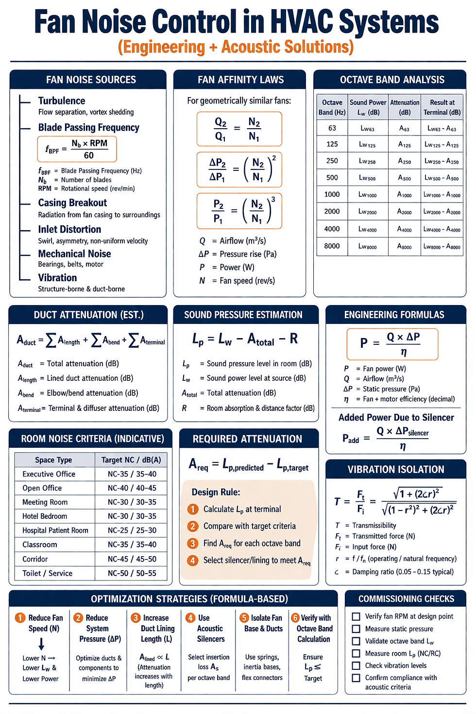
Fan noise in HVAC systems has several sources and transmission mechanisms.
Sound generation at the fan
The fan produces sound power due to aerodynamic and mechanical effects. The aerodynamic part is usually dominant in well-built equipment. Key contributors are:
blade passing frequency and harmonics
turbulence at blade tips
vortex shedding
inlet flow distortion
flow separation
stall or unstable operation
high tip speed
excessive pressure generation relative to fan type
Mechanical sources include bearing noise, motor noise, belt noise, and structural resonance.
The blade passing frequency is:
fBPF = (Nb×RPM)/60
Where:
fBPF = blade passing frequency, Hz
Nb = number of blades
RPM = rotational speed, rev/min
This matters because tonal noise near the blade passing frequency is often more objectionable than broadband noise.
Fan laws and acoustic implication
The affinity laws influence noise strongly. For geometrically similar fans:
Q ∝ N
ΔP ∝ N^2
P ∝ N^3
Where:
Q = airflow
ΔP = pressure rise
P = power
N = rotational speed
Sound power does not follow a single exact universal law in all cases, but in practical HVAC engineering, increasing fan speed significantly increases sound power. A small RPM increase can create a disproportionate acoustic penalty. This is why oversizing a fan and then throttling, or selecting a compact fan at high speed to save space, often produces a poor acoustic result.
Sound power vs sound pressure
Engineers must distinguish between sound power level and sound pressure level.
Sound power level (Lw) is the acoustic energy emitted by the source.
Sound pressure level (Lp) is what is measured in a specific receiving environment.
Manufacturers usually provide fan sound power by octave band. Room criteria are usually based on sound pressure in the occupied space. Converting one to the other requires analysis of attenuation, room absorption, distance, end reflection, breakout, and directivity.
Duct-borne noise and breakout
Noise travels both inside the duct and through the duct wall. Internal transmission reaches terminals and grilles. External breakout radiates into ceiling voids, adjacent rooms, or corridors.
High internal duct velocities, sudden transitions, sharp elbows close to the fan, and poorly selected dampers can all generate secondary noise. Therefore not all HVAC noise is “fan noise” even if the fan is the original source.
Structure-borne transmission
If the fan or connected ductwork transmits vibration into the structure, low-frequency noise can appear in remote spaces. This is often underestimated because the airside calculations may look acceptable while occupants complain of hum or rumble.
Frequency matters
A-weighted dB values alone are insufficient for engineering design. Low-frequency noise often causes disproportionate annoyance, while mid-frequency content can affect speech privacy and concentration. Octave-band analysis is therefore essential.
Code, Standards, and Compliance Context
Fan noise control should be aligned with project acoustic criteria and applicable standards. The exact requirements depend on project jurisdiction and specification, but in professional practice the following references are commonly relevant:
ASHRAE guidance
ASHRAE handbooks and applications guidance are widely used for HVAC acoustics, room noise criteria, duct design, and equipment sound data interpretation.
AHRI standards
AHRI standards are relevant for sound rating methods of HVAC equipment and provide a basis for comparing manufacturer data.
AMCA standards
AMCA standards are essential for fan performance and sound testing. Proper interpretation of AMCA sound ratings helps consultants compare equipment on a consistent basis.
ISO standards
ISO references are commonly used for acoustic measurement methodology, building acoustics, and evaluation of environmental or indoor sound performance.
Local building and environmental regulations
Some jurisdictions impose maximum indoor or outdoor noise limits, especially for façade discharge, smoke extract systems, rooftop plant, and boundary line noise.
Project-specific room criteria
In practice, the most important compliance framework is often the project acoustic brief.
Typical internal targets may be expressed as:
NC (Noise Criteria)
NR (Noise Rating)
RC (Room Criteria)
maximum dB(A) limits for specific spaces
A robust HVAC specification should state which metric governs acceptance. Saying “the system shall be quiet” is meaningless in contractual terms. Saying “occupied spaces shall not exceed NC-35 unless noted otherwise” is enforceable.
Design Methodology Step by Step
Step 1: Define room acoustic criteria
Start with the room function. Indicative targets may vary by project, but the principle is:
executive offices and high-end meeting rooms require lower background noise
hotel guestrooms require very low nighttime noise
hospitals require stringent criteria in patient and consultation spaces
corridors, toilets, and service spaces can tolerate higher levels
Do not apply one noise criterion to the entire building.
Step 2: Obtain reliable fan sound power data
Request octave-band sound power levels for inlet, discharge, and casing breakout where available. Do not rely only on one overall dB(A) number.
Also verify:
operating point
fan type
RPM
efficiency
motor size
whether the sound data is actual selected point data or catalog peak data
Step 3: Select the right fan, not only the right duty
From an acoustic viewpoint, preferred strategies often include:
lower rotational speed where practical
operation near best efficiency point
avoiding unstable regions
avoiding unnecessary system pressure
using fan type suitable for duty and acoustic expectation
A fan selected at the edge of its performance envelope is often noisy even if it meets airflow.
Step 4: Minimize system pressure at concept stage
Every unnecessary pascal creates acoustic and energy penalty. Reduce pressure by:
rational duct routing
controlled velocities
fewer abrupt transitions
proper AHU coil and filter selection
avoiding excessive safety margins stacked across disciplines
Noise control begins with pressure control.
Step 5: Evaluate transmission paths
Assess:
discharge path to critical rooms
inlet path and cross-talk
casing breakout into plantroom and ceiling void
structure-borne transfer
shaft transmission
terminal-generated noise
Step 6: Size attenuators only after reducing source strength
Silencers are important, but they should not compensate for poor fan selection. Determine required insertion loss by octave band after accounting for natural attenuation.
Step 7: Check air terminal and diffuser noise
VAV boxes, dampers, grilles, and diffusers can become dominant noise sources if pressures are high. A quiet fan feeding noisy terminals still results in a noisy room.
Step 8: Coordinate with architecture and structure
A lightweight partition beside a riser is an acoustic risk. A plantroom under a boardroom is a risk. A hotel FCU wall back-to-back with a bedroom headboard is a risk. HVAC acoustic success depends on layout decisions, not only calculations.
Step 9: Include commissioning and verification requirements
The design should define:
balancing conditions
acceptable fan speed range
vibration limits
room noise measurement conditions
background correction methodology
post-balancing acoustic verification
Detailed Engineering Calculation Example
Consider a supply fan serving a premium office floor.
Design data
Airflow: 12,000 L/s
Static pressure: 900 Pa
Fan type: backward-curved plenum fan
Fan speed: 1,450 rpm
Motor input: 18.5 kW
Manufacturer discharge sound power levels, dB re 1 pW:
Octave Band (Hz) | 63 | 125 | 250 | 500 | 1000 | 2000 | 4000 | 8000 |
Lw discharge | 87 | 85 | 83 | 81 | 78 | 74 | 69 | 64 |
Target in executive office: approximately equivalent to NC-35 range.
Assume the duct path from fan discharge to the critical office includes:
6 m lined duct: attenuation = 2, 4, 6, 8, 10, 12, 12, 10 dB
2 right-angle elbows: attenuation = 0, 1, 2, 3, 4, 4, 4, 4 dB
branch take-off and terminal effects before diffuser: attenuation = 1, 2, 3, 4, 5, 6, 6, 6 dB
diffuser end reflection / room end effect: attenuation = 0, 1, 2, 4, 6, 8, 10, 12 dB
Total natural attenuation:
Octave Band (Hz) | 63 | 125 | 250 | 500 | 1000 | 2000 | 4000 | 8000 |
Total attenuation | 3 | 8 | 13 | 19 | 25 | 30 | 32 | 32 |
Predicted sound power at diffuser entry:
Lw,terminal = Lw,fan − Attenuation
So:
Octave Band (Hz) | 63 | 125 | 250 | 500 | 1000 | 2000 | 4000 | 8000 |
Lw at terminal | 84 | 77 | 70 | 62 | 53 | 44 | 37 | 32 |
Now estimate room sound pressure contribution from the diffuser. A simplified engineering approximation for a typical furnished office may subtract room constant and terminal radiation effects by about 8 dB overall in mid bands for preliminary design. This is not a substitute for full acoustic software, but useful for design-stage screening.
Estimated Lp in room:
Octave Band (Hz) | 63 | 125 | 250 | 500 | 1000 | 2000 | 4000 | 8000 |
Approx. Lp | 76 | 69 | 62 | 54 | 45 | 36 | 29 | 24 |
This is likely too high for an executive office, especially in low and mid frequencies.
Required attenuation
Suppose the target octave-band room spectrum corresponding to the design criterion is approximately:
Octave Band (Hz) | 63 | 125 | 250 | 500 | 1000 | 2000 | 4000 | 8000 |
Target Lp | 55 | 45 | 38 | 35 | 32 | 30 | 28 | 25 |
Then the excess above target is:
Octave Band (Hz) | 63 | 125 | 250 | 500 | 1000 | 2000 | 4000 | 8000 |
Excess | 21 | 24 | 24 | 19 | 13 | 6 | 1 | 0 |
This indicates that natural attenuation is not enough. An attenuator may be required, but observe the pattern: the real problem is low and mid-frequency energy. A standard short silencer may not provide enough low-frequency insertion loss without significant length and pressure drop.(Fan Noise Control in HVAC Systems)
Engineering interpretation
This is where good design judgement matters. There are at least four possible interventions:
Option 1: Add attenuator (Fan Noise Control in HVAC Systems)
Possible, but may add 40–100 Pa pressure drop depending on size and performance.
Option 2: Reduce fan speed by improving system pressure design
If system pressure can be reduced from 900 Pa to 700 Pa through better duct routing and component selection, fan speed and sound power can drop materially.
Option 3: Increase duct attenuation length and lining strategy
Longer lined duct near the fan discharge, if acoustically acceptable and hygienically appropriate for the application, may reduce required attenuator size.
Option 4: Re-select a larger, slower fan
This often yields the best combined acoustic and energy outcome.
Pressure drop and energy effect of a silencer
Suppose adding a silencer introduces 60 Pa extra pressure. Additional fan power:
P = (Q×ΔP)/η
Where:
Q=12,000 L/s=12 m3/s
ΔP=60 Pa
overall efficiency η=0.65
P = (12×60)/0.65 = 1107.7 W
Additional electrical power is about 1.11 kW.
If the fan operates 3,500 hours/year:
E = 1.11×3500 =3 885 kWh/year
At electricity cost of 0.12 USD/kWh:
Cost = 3885×0.12 = 466.2 USD/year
For one fan this may appear manageable, but across multiple AHUs the lifecycle cost becomes significant. This is why source reduction is often financially superior to late-stage attenuation.
Real Project Scenario
Consider a premium mixed-use development in a hot climate with office floors above retail podium. The office tenant on level 5 complains of constant HVAC noise in meeting rooms. Thermal conditions are acceptable. Measurements show elevated noise centered around 125 Hz and 250 Hz with intermittent tonal character.
Investigation findings
Supply fan selected at high static pressure with limited margin
Fan operating above initial expected speed due to dirty filters and balancing adjustments
Discharge attenuator added late due to lack of acoustic allowance in concept design
Flexible connector installed, but rigid duct supports bridged vibration downstream
First elbow placed too close to fan discharge
Meeting rooms located adjacent to main supply duct and shaft wall
VAV boxes serving rooms operating at high inlet pressure
Root cause
The acoustic problem was not one item. It was a system problem. The fan selection, duct geometry, structural connection, and terminal pressure conditions all contributed.
Corrective actions
Reduced branch velocities and rebalanced VAV minimum settings
Reconfigured first discharge elbow with proper straight length
Added resilient duct support sections at critical points
Upgraded shaft wall treatment and sealed leakage paths
Reprogrammed static pressure reset logic to reduce fan speed at part load
Replaced two high-noise VAV boxes with lower-pressure-drop models
Result
Room noise reduced to acceptable range without full fan replacement. Energy use also improved because the revised control sequence lowered average fan speed.
The lesson is important: acoustic correction is most successful when it targets the full chain of cause, not just the symptom.
Design Risks, Failure Modes, and Common Mistakes
Overspecifying safety margins
Consultants often stack hidden margins into duct friction, coil pressure drop, filter allowance, terminal allowance, and future flexibility. The final fan static becomes inflated, increasing fan speed, sound power, and energy use.
Using attenuators as a substitute for proper selection
Silencers are tools, not rescue devices. If the source sound power is excessive, attenuation becomes bulky and expensive.
Ignoring low-frequency behavior
Low-frequency noise is harder to attenuate and often transmitted structurally. Designs based only on dB(A) values miss this risk.
Poor inlet conditions
Fans need stable inlet flow. Swirl, asymmetry, and abrupt approach geometry increase turbulence and noise.
Sharp elbows near fan discharge
Close-coupled elbows create turbulence, regenerate noise, and impair performance.
High duct velocities in critical branches
Even if the main fan is acceptable, branch hiss and terminal turbulence can dominate room noise.
Incorrect flexible connection detail
A flexible connector alone is not enough if supports, rods, or rigid accessories short-circuit the isolation path.
Plantrooms under sensitive spaces
This layout decision creates preventable risk. Once construction progresses, mitigation becomes expensive.
Treating acoustics as a late-stage specialist issue
By the time the acoustic consultant is asked to solve the problem, the geometry, plant space, and equipment selection may already be locked.
Optimization Strategies
Reduce source noise first
This is the highest-value strategy. Use larger, slower fans where feasible. Select fans near peak efficiency. Avoid unstable regions.
Design lower-pressure systems
A low-pressure airside design usually improves both energy and acoustics. This requires discipline in routing, fittings, and component selection.
Use static pressure reset
At part load, many systems do not need full static pressure. Intelligent control reduces average fan speed and therefore average noise.
Apply attenuation selectively
Do not put large silencers everywhere by default. Target critical paths and critical spaces.
Separate noisy plant from sensitive spaces
Good planning is cheaper than heroic attenuation.
Control terminal pressure
VAV box and diffuser noise can often be reduced by proper branch design and realistic minimum pressure targets.
Verify casing breakout
In some installations, casing breakout to plenum or plantroom dominates. External lagging or room treatment may be more effective than more internal attenuation.
Cost, Energy, and ROI Perspective
From a developer or asset-owner perspective, fan noise control has three economic dimensions.
Capital cost
Better fan selection, more plantroom space, larger duct sections, acoustic lining, and vibration isolation may increase initial capex modestly.
Operating cost
Poor acoustic fixes often add pressure drop and therefore fan energy. Better source design usually reduces lifecycle energy.
Corrective and reputational cost
Noise complaints consume consultant time, contractor resources, facility management effort, and occupant goodwill. In premium assets, acoustic failure can affect tenancy, branding, and user retention.
A financially intelligent design does not chase the cheapest first cost. It seeks the lowest total cost of ownership while maintaining comfort and value. For example, upsizing a fan section to reduce RPM may cost more initially but avoid attenuator size, reduce motor power, lower energy, and improve occupant experience. That is strong engineering and good commercial judgement.
Advanced Engineering Insights
Tonal noise is often more objectionable than broadband noise
Two systems with similar dB(A) may be perceived very differently. Blade passing tones, motor harmonics, and resonance peaks demand special attention.
Acoustics and aerodynamics are inseparable
Any feature that degrades flow quality usually degrades acoustic quality. Good flow design is often good acoustic design.
Part-load behavior matters
Some systems are quiet at design duty but noisy at part load due to VFD resonance, control instability, or dampers operating in poor positions. Acoustic review should consider operating range, not one point only.
Vibration isolation requires system thinking
Spring isolators, inertia bases, flexible connectors, and resilient supports must work together. One rigid bypass can compromise the entire isolation strategy.
Ceiling plenums are not guaranteed acoustic buffers
A shared plenum can become a transmission path. Sound can travel above partitions and re-enter remote rooms.
Smoke extract and car park fans are special cases
These systems often operate at high pressure and high velocity, with less stringent day-to-day running expectations but major regulatory importance. If they operate intermittently near occupied zones, acoustic impact still matters and should be addressed separately from comfort AHUs.
Specification and Coordination Considerations
A tender-grade specification should require the following:
Acoustic performance criteria by room type
State target NC/NR/RC or equivalent maximum levels for each relevant space category.
Equipment submittals
Require octave-band sound power data for fan inlet, discharge, and casing breakout at actual selected duty.
Vibration isolation details
Specify isolator type, static deflection, flexible connections, inertia base where required, and resilient support details for connected services.
Duct acoustic treatment
Define where lined duct, attenuators, lagging, and acoustic enclosures are required, with hygiene and fire compliance considered.
Maximum air velocities
Set rational limits for main ducts, branches, terminal necks, return paths, transfer grilles, and louvers in acoustically sensitive applications.
Installation quality
Require straight lengths at fan inlet/discharge as recommended by manufacturer and design intent. Prohibit rigid short-circuiting of isolators.
Testing and commissioning
Require post-balancing acoustic verification in representative occupied spaces and define remediation responsibility if criteria are not met.
Coordination with other disciplines
Architectural partitions, slab openings, shaft walls, doors, ceiling systems, and plantroom finishes must support the acoustic strategy. HVAC acoustics cannot succeed if the architectural separation is weak.
FAQ
What is the most common reason HVAC fans become too noisy?
Usually excessive system pressure combined with fan selection at high speed. The symptom may appear at the room diffuser, but the root problem often starts with pressure and fan operating point.
Is adding a silencer always the best solution?
No. It may solve part of the problem, but it increases pressure drop and energy use. Source reduction is usually better when feasible.
Why is octave-band data necessary?
Because sound control measures do not attenuate all frequencies equally. Low-frequency problems cannot be judged correctly from one overall dB(A) value.
What is more important: fan type or fan speed?
Both matter, but speed is often the bigger acoustic driver in real HVAC applications.
Can duct lining alone solve fan noise?
Sometimes for mild cases in mid to high frequencies, but not usually for strong low-frequency or tonal issues.
Why do occupants complain even when measured dB(A) is not very high?
Because tonal content, low-frequency rumble, intermittency, or vibration can be more annoying than the overall number suggests.
How do VAV boxes affect fan noise control?
They can become major local noise generators if upstream pressure is high or if selection is poor.
Are flexible duct connectors enough for vibration isolation?
No. They help, but the whole support and connection system must be isolated properly.
Why is low-frequency noise so difficult?
Because it travels farther, attenuates less in many treatments, and is often transmitted structurally.
Should acoustics be checked only for full-load operation?
No. Part-load and control-sequence behavior can be equally important.
Can plantroom location solve many acoustic issues before they start?
Yes. Good space planning is one of the most powerful acoustic strategies available.
Does quieter design usually mean higher energy use?
Not necessarily. Often the opposite is true. Lower pressure and lower speed improve both acoustics and energy performance.
What should consultants request from fan manufacturers?
Actual selected-point octave-band sound power data, not just catalog summaries.
How should acceptance be written in the specification?
With measurable room acoustic criteria, defined measurement method, and clear responsibility for compliance after TAB and final balancing.
Conclusion
Fan noise control in HVAC systems is an engineering discipline that sits at the intersection of aerodynamics, acoustics, controls, structural isolation, and practical construction coordination. It should never be treated as a cosmetic adjustment after fan duty has already been finalized. By the time the building is occupied, acoustic defects are expensive to diagnose, politically difficult to manage, and technically harder to fix.
The correct approach is deliberate and layered. First, control sound power at source through intelligent fan selection, realistic pressure design, and efficient operating points. Second, control transmission through good duct geometry, appropriate attenuation, and robust vibration isolation. Third, protect receiving spaces through sensible planning, architectural coordination, and clear room criteria. Finally, verify performance through proper commissioning and acoustic testing.
For MEP engineers and consultants, this topic is commercially important because it separates commodity design from premium design. Any engineer can produce airflow and pressure schedules. Higher-value engineering is demonstrated when the delivered system is also quiet, stable, energy-conscious, maintainable, and comfortable in real operation. That is what owners remember. That is what occupiers feel every day. And that is where technically strong HVAC design becomes financially valuable.
Author’s Note
This article is intended for engineering guidance only. Final fan acoustic design must be based on project-specific room criteria, validated manufacturer data, applicable codes and standards, architectural construction details, and where necessary, specialist acoustic analysis. The correct solution in one project may be inappropriate in another due to differences in occupancy type, structural configuration, plant arrangement, and contractual requirements.


Comments