Chilled Water Pump System Design Guidance
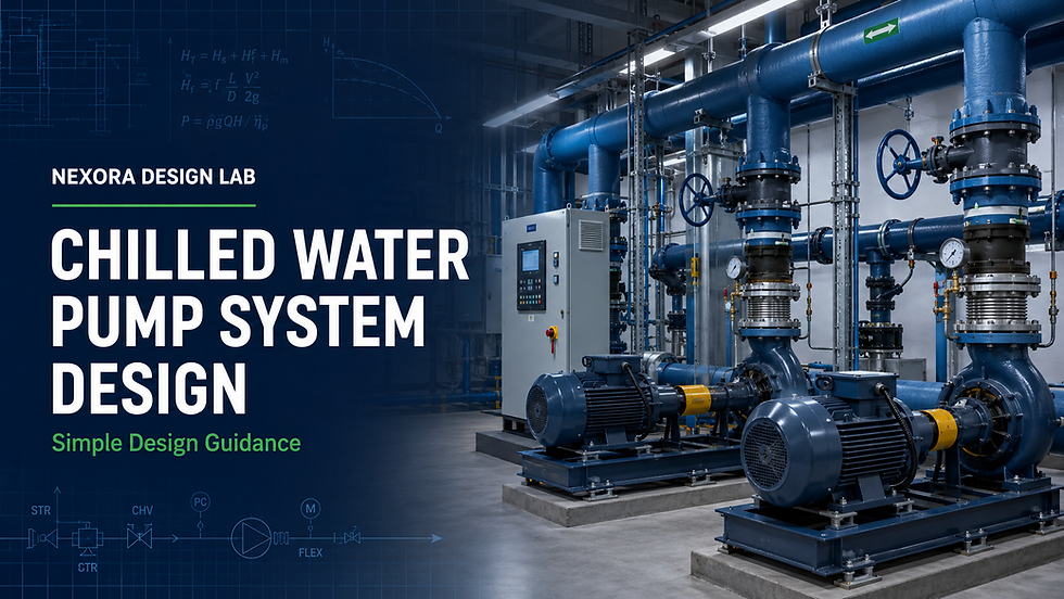
A chilled water pump must circulate the required water flow through the system while overcoming pipe, fitting, valve, coil and equipment pressure losses.
Correct pump selection improves cooling performance, reduces energy consumption and prevents common problems such as insufficient flow, noisy valves, low chilled-water ΔT and excessive pump power. (Chilled Water Pump System Design Guidance)
Need a Faster Way to Calculate Pump Head?
Use the Nexora Pump Head Calculator to simplify chilled water pipe, fitting, valve and equipment pressure-loss calculations.
1. Determine the Chilled Water Flow Rate
The required chilled water flow depends on the cooling load and the selected chilled water temperature difference.
For water:
Water Flow (m³/h) = Cooling Load (kW) ÷ [1.163 × ΔT (°C)]
Example
Cooling load = 500 kW
Chilled water supply temperature = 7°C
Chilled water return temperature = 13°C
Design ΔT = 6°C
Water Flow = 500 ÷ (1.163 × 6)
Required Water Flow = 71.7 m³/h
The cooling load must be calculated correctly before selecting the pump.
2. Select the Pumping Arrangement
The chilled water pumping arrangement depends on the system size, chiller requirements and control method.
Constant Primary Flow
The pump maintains constant flow through the chiller and distribution system. This arrangement is simple and suitable for smaller systems with relatively stable loads.
Primary–Secondary Pumping
Primary pumps maintain the required flow through the chillers, while secondary pumps distribute chilled water to the building.
This arrangement is commonly used for multiple-chiller and large chilled water systems.
Variable Primary Flow
The same pumps circulate water through the chillers and building distribution system. Pump speed is controlled using variable-frequency drives.
Variable primary flow can reduce pump energy, but minimum chiller flow and control requirements must be carefully maintained.
3. Size the Chilled Water Pipes (Chilled Water Pump System Design Guidance)
Pipe sizing must consider:
Design water flow
Water velocity
Pipe friction loss
Noise
Available pump head
Future operating conditions
Pipe material
Water or glycol concentration
Common preliminary design ranges are:
Main chilled water pipes: approximately 1.0–2.5 m/s
Small branches: approximately 0.6–1.5 m/s
Pipe friction rate: approximately 100–400 Pa/m
These are starting values only. Always verify them against the project specification, equipment requirements and applicable design standards.
4. Identify the Index Circuit
The pump must overcome the pressure loss through the hydraulically most demanding circuit.
This is not always the longest pipe route. It is the route with the highest combined resistance.
The index circuit may include:
Chilled water supply pipe
Chilled water return pipe
Elbows, tees and reducers
Isolation and check valves
Strainers
Balancing valves or PICVs
Control valves
Cooling coil
Chiller or heat exchanger
Other inline accessories
Every relevant component must be included in the calculation.
5. Calculate the Total Pump Head
The total pump head is the sum of the pressure losses along the index circuit.
Total Pressure Loss = Pipe Loss + Fitting Loss + Valve Loss + Coil Loss + Equipment Loss
For water:
Pump Head (m) = Total Pressure Loss (kPa) ÷ 9.81
Simple Example
Pipe and fitting loss = 65 kPa
Cooling coil loss = 35 kPa
Chiller loss = 45 kPa
Control and balancing valve loss = 25 kPa
Strainer and accessories = 15 kPa
Total Pressure Loss = 185 kPa
Pump Head = 185 ÷ 9.81 = 18.9 m
The preliminary pump duty would therefore be:
Flow: 71.7 m³/h
Head: 18.9 m
Any design allowance should be justified and applied only after the actual system losses have been calculated.
Important: In a closed chilled water loop, the building height is normally not added to the operating pump head. The rising and falling static pressures balance each other. Static pressure must still be considered when designing the pressurization system and checking pump suction conditions.
6. Select the Chilled Water Pump
Select a pump capable of operating at the calculated flow and head.
Check the following before final selection:
Pump duty point
Pump efficiency
Best efficiency point
Pump curve
Motor power
Variable-frequency drive compatibility
Net positive suction head
Maximum and minimum operating flow
Chilled water temperature
Pump material and pressure rating
Duty and standby requirements
Avoid selecting an unnecessarily oversized pump. Oversized pumps can increase energy consumption, valve noise and system balancing problems.
7. Estimate Pump Motor Power
The approximate hydraulic power can be calculated using:
Hydraulic Power (kW) = ρ × g × Q × H ÷ 1,000
Where:
ρ = Water density in kg/m³
g = 9.81 m/s²
Q = Water flow in m³/s
H = Pump head in metres
The motor input will be higher because pump, motor and drive efficiencies must be considered.
8. Plan the Pump Controls
Variable-speed chilled water pumps are commonly controlled using a differential-pressure sensor.
A suitable control system may include:
Variable-frequency drive
Differential-pressure sensor
Two-way control valves or PICVs
Minimum chiller flow protection
Pump sequencing
Duty and standby changeover
Differential-pressure setpoint reset
BMS monitoring and alarms
The differential-pressure sensor should be located near the hydraulically critical circuit, not automatically beside the pump.
9. Verify the System During Commissioning
Before final handover, verify:
Actual pump flow
Pump differential pressure
Pump rotation
Motor current
Valve operation
Coil water flow
Chilled water supply and return temperatures
System ΔT
Air removal
Strainer cleanliness
VFD operation
Duty and standby sequencing
A correct calculation must always be supported by proper testing and balancing.
Common Chilled Water Pump Design Mistakes
Avoid these common errors:
Adding the full building height to a closed-loop pump head
Selecting the longest route without checking total resistance
Ignoring fittings, valves and strainers
Omitting coil or chiller pressure losses
Applying excessive safety factors
Selecting the pump only from the pipe connection size
Locating the differential-pressure sensor incorrectly
Ignoring the chiller’s minimum flow requirement
Using the wrong chilled water ΔT
Ignoring glycol effects on flow and pressure loss
Oversizing pumps to compensate for incomplete calculations
Complete Your HVAC Design More Confidently
A chilled water pump is only one part of the complete HVAC system. The cooling load determines the required water flow, the hydraulic calculation determines pump head, and the airside design determines how cooling is delivered to each space.
Choose the Nexora resource that matches your next design task:
Calculate chilled water system pressure losses and establish the required pump duty more efficiently.
Learn how to determine room, zone, system and equipment cooling loads using a structured design process.
Build a practical foundation in HVAC systems, equipment, terminology and design principles.
Speed up duct sizing and airside pressure-loss calculations for HVAC fan and duct system design.
Final Design Checklist
Before issuing the chilled water pump selection, confirm:
Cooling load is approved
Design chilled water ΔT is confirmed
Required water flow is calculated
Pipe sizes and velocities are checked
Index circuit is identified
Pipe and fitting losses are included
Valve and equipment losses are included
Pump curve and efficiency are reviewed
Minimum chiller flow is protected
Control and commissioning requirements are defined
Design faster. Reduce calculation errors. Produce more professional HVAC submissions with Nexora Design tools.
This article provides general engineering guidance. Final calculations and equipment selections must comply with the project specifications, equipment manufacturers’ requirements and applicable local standards.


Comments