Control-Valve Close-Off Pressure: Catch the Actuator Submittal Mismatch
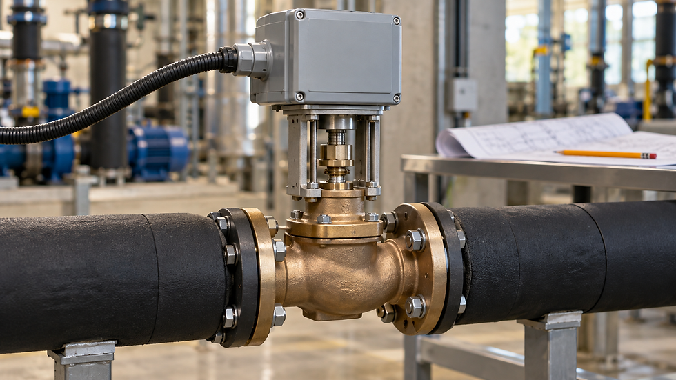
AI-generated editorial illustration; not a verified installation or construction detail.
A small pressure entry can hide a large mismatch
A control-valve schedule lists 35 kPa pressure drop at design flow. The submitted valve-actuator assembly has a 300 kPa close-off rating. That looks comfortable until the reviewer checks a credible low-flow pump condition capable of imposing about 411 kPa across the closed valve.
The correct review uses separate entries for flow-sizing pressure drop, maximum operating differential, close-off differential and body pressure rating. Treating them as interchangeable can approve an assembly that passes its flow calculation but cannot meet the required shutoff duty.
Read each rating as a different question
Design valve pressure drop is the loss assigned to the open control valve at a specified flow and opening condition. It supports capacity and controllability calculations. Record the actual condition rather than assuming every schedule means fully open.
Close-off pressure describes the differential against which the complete valve-actuator assembly can maintain the specified closed-valve leakage performance. Body pressure rating concerns containment at the applicable fluid temperature. Belimo distinguishes these checks in its Electronic Valve Applications Guide. A body pressure rating alone does not establish seat shutoff capability.
Maximum operating differential is another limit. Siemens’ valve and actuator selection documentation distinguishes closing pressure from differential pressure allowed through the actuating range. Read the definition for the selected product; a large close-off number does not automatically permit continuous modulation at that same differential.
The choice of hydraulic arrangement comes first. See Nexora’s two-way and three-way valve overview for that separate decision. This review assumes the intended valve arrangement has already been established.
Find the maximum credible pressure difference at this valve
Start with an annotated hydraulic schematic and the actual control sequence. Identify the supply and return nodes connected to the valve, the pumps that can operate, their maximum permitted speed, and any pressure-control or pressure-break equipment between them.
Consider normal operation, low demand, startup, permitted manual operation and the specified response to failed pressure sensing or loss of controls. A normal BMS differential-pressure setpoint is insufficient evidence of a hard pressure limit if an allowed mode can drive the pump beyond it.
For an ordinary closed coil branch, friction losses through the coil and connecting pipes approach zero as branch flow approaches zero. Those design-flow losses cannot simply be subtracted from the closed-valve duty. Common-header losses depend on the flow in other branches and need their own assessment.
Maximum-speed pump shutoff head can provide a conservative screening boundary where the valve can experience that differential. It is not automatically the correct value in a different pressure zone, a district interface or a circuit with additional pumps. Use the actual topology and approved operating envelope.
Work the original submittal example
Assume an ordinary two-port valve on a near-plant chilled-water coil branch. Design flow is 1.8 L/s. At that flow the scheduled losses are 35 kPa through the control valve, 45 kPa through the coil and 20 kPa through the branch piping and accessories: 100 kPa in total.
For this teaching example, the reviewed operating envelope includes a credible maximum-speed, low-flow condition approaching the pump’s 42.0 m shutoff head. No independent differential-pressure limiter caps the valve pressure, and header losses are negligible in this limiting case. Use water density 998 kg/m³ and g = 9.81 m/s².
Maximum screening differential = ρgH ÷ 1,000 = 998 × 9.81 × 42.0 ÷ 1,000 = 411.20 kPa.
Hypothetical candidate A has a manufacturer-confirmed assembly close-off rating of 300 kPa. It falls short by 411.20 − 300 = 111.20 kPa. Comparing 300 kPa with the 35 kPa design valve loss would have missed the mismatch. Subtracting the original 45 + 20 kPa branch losses would also be wrong at closed-valve flow.
Hypothetical replacement B has a confirmed 600 kPa close-off rating for the required closing mode. It clears this preliminary 411.20 kPa comparison. Final acceptance still needs the project’s required allowance, permissible operating differential, temperature, leakage class, installation direction and complete model-specific conditions.
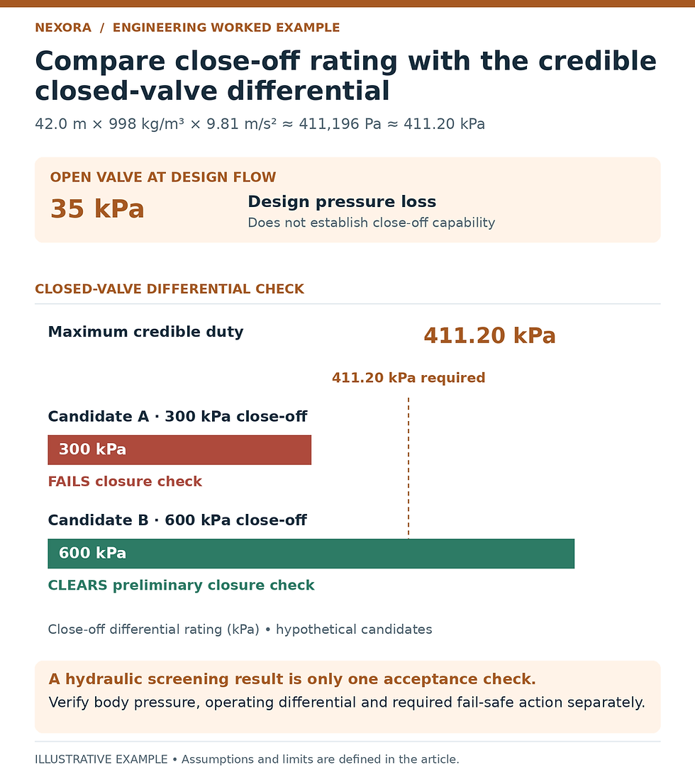
All candidate ratings are hypothetical. A 35 kPa design loss does not establish close-off duty. Check operating differential, body pressure and required fail-safe action separately.
Check the body and fail-safe function separately
Suppose the highest credible return-side pressure at the example valve is 420 kPa gauge, coincident with the limiting pump differential. The high side could reach approximately 420 + 411.20 = 831.20 kPa gauge. A hypothetical 1,600 kPa allowable body pressure at the actual temperature clears that simplified steady-state containment check.
That arithmetic neither approves the valve for pressure testing nor covers surge, thermal expansion in trapped sections or different fill conditions. Those belong in the project pressure envelope. Record what the assumed 420 kPa represents rather than using an unlabelled “system pressure” entry.
Fail-safe selection also needs the exact assembly. Belimo’s globe-valve technical documentation tabulates close-off values by valve and actuator family, including different return mechanisms. A replacement with suitable powered operation may still require separate confirmation for spring or electronic fail-safe action.
If a hypothetical assembly is confirmed for 600 kPa under powered closing but only 350 kPa in the required fail-safe closing mode, it does not satisfy this example’s 411.20 kPa fail-safe duty. Ask the supplier for the applicable rating instead of inferring it from actuator torque or thrust alone.
Turn the discrepancy into a specific review comment
A useful comment identifies the valve tag, complete submitted valve and actuator codes, calculated maximum differential and the missing or insufficient rating. Request the manufacturer’s approved combination table or selection output for the specified medium, temperature, flow direction and failure action.
For example: “Valve CV-17 is scheduled at 35 kPa design loss. Hydraulic review gives 411.2 kPa maximum credible closed-valve differential. Submitted assembly A is rated 300 kPa close-off. Revise the assembly or provide a coordinated, approved pressure-limitation design, and demonstrate operating and fail-safe compliance.”
Changing the actuator may affect mounting, power supply, control signal, stroke time and fail position. Changing pump limits may affect remote-coil flow and equipment minimum-flow protection. Close the review across the affected disciplines rather than replacing one number in the valve schedule.
Verify the operating behavior without creating a test hazard
An assembly that holds shut may still be unsuitable when modulating under excessive differential. Spirax Sarco’s water control-valve guidance discusses how pressure conditions and water temperature relate to cavitation. Check model-specific acoustic and cavitation limits where relevant.
Use an approved commissioning procedure to verify command, travel feedback and shutoff behavior under permitted conditions. A position signal saying “closed” does not measure leakage. Do not deliberately deadhead the plant or bypass protections just to reproduce a theoretical limiting case.
Keep field pressures on a clear reference basis. Nexora’s fill-pressure and pump differential-head explanation helps distinguish local gauge pressure from circulating differential.
Close-off submittal checklist
Record valve tag, complete body code, actuator code and approved pairing.
Separate design flow loss, maximum operating differential, close-off rating and allowable body pressure.
Document the maximum credible hydraulic condition and any pressure-limiting assumptions.
Confirm leakage requirement, flow direction, fluid temperature and required failure action.
Resolve changed power, controls, mounting and pump-sequence requirements.
Retain the reviewed selection and safe commissioning evidence with the valve schedule.
A defensible approval connects each rating to the condition it must withstand.
Related learning resource
For broader coordination between pumps, pipework and control valves, explore Nexora’s Chilled Water System Design Handbook. Use the selected manufacturer’s assembly ratings for final approval.
Sources and further reading
Engineering education only. Verify project conditions, applicable requirements and manufacturer data; use qualified professional judgment before design, selection, operation or maintenance decisions.


Comments