Cooling-Coil Bypass Factor and Apparatus Dew Point: A Selection Sanity Check

AI-generated editorial illustration; not a verified installation or construction detail.
Use the model to question a selection
Cooling-coil bypass factor helps describe how closely leaving air approaches an effective saturated coil condition. It is useful for a quick psychrometric reasonableness check. It cannot independently select coil rows, fin spacing, water flow or a refrigerant circuit. Those require an actual performance selection.
Start by asking for entering and leaving dry-bulb temperature and humidity ratio, air mass flow, fluid conditions and the point at which each air state applies. A leaving-air temperature alone does not establish dehumidification performance. The example below shows why an apparently small change in bypass factor matters.
What apparatus dew point means
ASHRAE defines apparatus dew point, or ADP, as the effective coil surface temperature during dehumidification. In the simplified model, it is represented by a point on the saturation curve. It is neither automatically the entering chilled-water temperature nor a measured uniform temperature on every fin. See ASHRAE Terminology.
A real coil has changing air and fluid temperatures along its depth and circuits. Some portions may be dry while others remove moisture. The purpose of the effective condition is to represent the overall process, not to pretend that the coil is isothermal.
On a psychrometric chart, the idealized entering-to-leaving process extends toward the ADP. If a proposed pair of air states implies an implausible saturated intersection, investigate the inputs and selection basis. Do not fix the mismatch by silently choosing a more convenient ADP.
Bypass factor is an effectiveness model
For the wet-coil approximation, the enthalpy form is BF = (h leaving − h ADP) / (h entering − h ADP). The corresponding humidity relation is w leaving = w ADP + BF × (w entering − w ADP). A smaller BF moves the leaving state closer to the effective saturated condition.
This is a conceptual mixing representation. A calculated BF of 0.15 does not prove that 15% of the real air physically flows through an open gap around the coil. Genuine casing bypass or uneven face velocity is a different installation issue that still needs inspection.
The EnergyPlus engineering reference uses ADP and bypass-factor methods in coil models and adjusts the factor with airflow. Accordingly, a value calculated at one operating point should not be treated as a fixed guarantee at every fan speed or load.
Worked example with consistent heat and moisture balances
Assume a simplified fully wet coil at 101.325 kPa atmospheric pressure. Entering air is 27°C with w = 0.01350 kg/kg dry air. Dry-air mass flow is 2.00 kg/s. Assume ADP = 10°C, with saturated humidity ratio rounded to 0.00763 kg/kg, and BF = 0.15. These are illustrative assumptions, not a catalog rating.
Use h = 1.006T + w(2501 + 1.86T), in kJ/kg dry air. Entering enthalpy is 61.603 kJ/kg and ADP enthalpy is 29.285 kJ/kg. The model gives leaving enthalpy 29.285 + 0.15 × (61.603 − 29.285) = 34.132 kJ/kg.
Leaving humidity ratio is 0.00763 + 0.15 × (0.01350 − 0.00763) = 0.0085105 kg/kg. Solving the same enthalpy equation for temperature gives T = (h − 2501w)/(1.006 + 1.86w), or approximately 12.57°C. This keeps the temperature and moisture calculation on one basis.
Air-stream total cooling is 2.00 × (61.603 − 34.132) = 54.94 kW. Condensate production is 2.00 × (0.01350 − 0.0085105) × 3600 = 35.92 kg/h. The simplified cooling result neglects condensate enthalpy and external heat transfer. Both results require steady conditions and a correctly defined dry-air mass flow.
The common temperature-ratio approximation gives 12.55°C for this example, close to 12.57°C. The small difference arises because moist-air enthalpy also depends on humidity ratio. Retain sensible rounding rather than reporting hundredths as guaranteed selection accuracy.
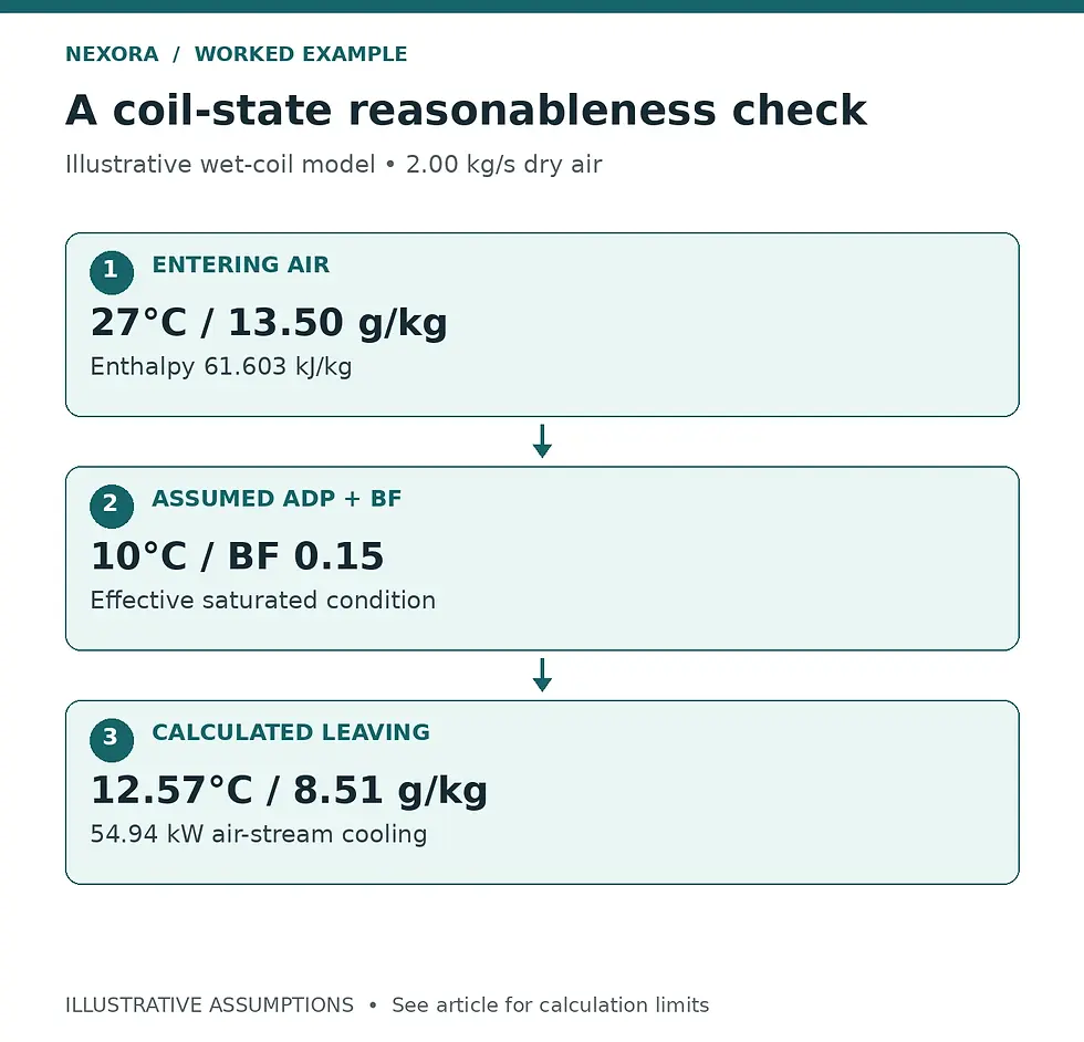
Original schematic of the example calculation. ADP is an effective condition; it is not automatically entering water temperature.
Sensitivity: a warmer, wetter leaving state
Now change only the illustrative bypass factor from 0.15 to 0.30, keeping the assumed ADP and entering state fixed. Leaving humidity ratio becomes 0.009391 kg/kg, enthalpy becomes 38.980 kJ/kg, and temperature is about 15.14°C. Air-stream cooling falls to 45.25 kW and moisture removal to 29.58 kg/h.
This sensitivity isolates the model’s response. It does not predict how a particular installed coil changes when airflow changes, because real ADP, fluid temperature, heat-transfer coefficients and available capacity can change together. Ask the manufacturer to rerun the required operating points.
For a humidity-sensitive room, compare the resulting supply humidity ratio with the room moisture balance, including outdoor air, occupants and infiltration. Reheat can change dry-bulb temperature without removing additional moisture; it cannot turn a too-wet coil leaving state into a drier one.
Review the physical selection as well as the numbers
The ASHRAE air-cooling coil chapter describes wet and dry operation, circuit arrangements and air-distribution concerns. For a submittal review, record coil face area, selected air velocity, air and water pressure drops, fluid composition, water temperatures and capacity at the stated airflow.
Confirm that the selected fan can deliver the required airflow through the actual coil and filters. Keep coil-leaving and unit-supply conditions separate when the fan adds heat downstream. Check drain-pan, access and carryover provisions using the manufacturer’s installation requirements.
Request at least the peak sensible case and a credible high-moisture or part-load case when the application needs humidity control. A single peak-load point can conceal a different operating condition that governs the required supply dew point. Manufacturer performance and the approved control sequence remain the acceptance basis.
A short calculation handover
Keep the raw air states, atmospheric pressure, dry-air mass flow, property method, ADP assumption and BF together on the calculation sheet. Show whether BF was assumed for teaching, inferred from a selection, or provided by the manufacturer. That distinction prevents a screening value from becoming a procurement requirement by accident.
If calculated BF is outside a physically meaningful range, or leaving humidity exceeds the entering value during supposed dehumidification, stop and reconcile units and sensor locations. Use PsychroLib’s documented property functions or another validated psychrometric method; avoid mixing charts drawn for different pressures.
Related learning resource
For the broader load-to-airflow and coil-duty workflow, see Nexora’s Cooling Load Design Handbook. Use this worked screen alongside, rather than in place of, project-specific manufacturer selections.
Sources and further reading
Engineering education only. Verify project conditions, applicable requirements and manufacturer data; use qualified professional judgment before design, selection, operation or maintenance decisions.


Comments