Exhaust Fan Running but Airflow Is Low? Check the Makeup-Air Path

AI-generated cover image for illustration.
A fan can be running while the room receives inadequate exhaust. Before increasing fan speed or buying a larger unit, trace the air that must replace the exhausted volume. A blocked supply, closed transfer path or changed door arrangement can make the fan work against a resistance that was missing from the design assumption.
This guide concerns ordinary comfort ventilation and general exhaust. Smoke control, laboratories, healthcare isolation, hazardous exhaust and combustion-appliance spaces need their applicable specialist procedures. Do not alter protected pressure relationships or life-safety settings as a troubleshooting shortcut.
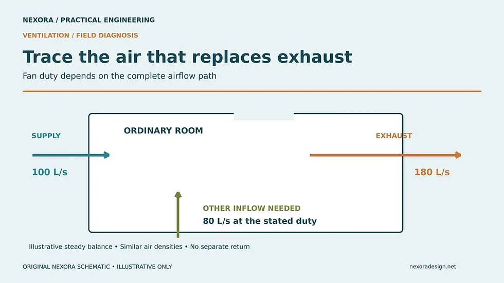
Original Nexora schematic. Illustrative only; not a construction or commissioning detail.
Think in complete air paths
Follow air from its intended source, through the room and into the exhaust system, then through the duct and discharge. The fan and duct are only part of that route. Replacement air may arrive through a mechanical supply, an engineered transfer opening or a combination of paths.
Greenheck's fan-selection guidance notes that insufficient makeup air increases system resistance and reduces exhaust flow. Consequently, a fan's catalogue airflow is not proof of the installed airflow.
A pressure difference is what drives transfer through an opening. The opening's resistance determines how much air passes at that pressure. A nominal door gap or grille size therefore cannot confirm the flow without the relevant performance data or measurement.
For the separate design calculation, see Nexora's toilet exhaust ventilation guide. The investigation here is about why a completed system fails to achieve its intended duty.
Define the complaint before touching controls
Record which rooms are affected, when the problem occurs and what changed. Check whether the complaint appears only with doors shut, at particular occupancy levels or when another exhaust system operates. Compare occupied and unoccupied modes without assuming that both should use the same duty.
Ask what "not working" means: low measured volume, poor source capture, persistent moisture, an odour complaint or excessive negative pressure. These are related but different observations. Odour alone does not quantify ventilation, and extra airflow will not repair a drain, remove a spill or fix an exhaust discharge re-entering the building.
Obtain the approved airflow schedule and sequence before judging performance. If those are unavailable, identify the gap for the designer or responsible engineer instead of inventing a target.
Check the fan-side causes too
A makeup-air restriction is one possible cause. Qualified personnel should also check the operating command, actual speed, fan rotation where relevant, dirty or damaged components, damper operation, duct obstruction and discharge condition under the approved maintenance procedure.
Greenheck's fan-performance troubleshooting guidance lists mechanical faults and airflow obstructions among reasons installed fans miss their duty. Avoid treating the electrical "run" indication as an airflow measurement.
Poor inlet or outlet geometry can create an additional system effect. Greenheck's system-effects explanation shows why nearby obstructions and unsuitable connections can degrade performance and make reliable field readings difficult. Where needed, have the test location and installed fan arrangement reviewed together.
Measure a room balance on one consistent basis
For an ordinary room at approximately steady conditions, the total air entering and leaving must balance by mass. At similar densities, a volume balance provides a useful field approximation. Include mechanical supply, exhaust, return and intentional transfer paths; do not compare only the two easiest grilles to reach.
Consider this illustrative schedule: 180 L/s exhaust, 100 L/s mechanical supply and no separate return. About 80 L/s must enter through other paths at the intended operating condition, assuming similar air densities. If the planned transfer path is blocked, the actual fan flow and room pressure can settle at a different operating point.
Do not interpret the 80 L/s as permission to add an arbitrary door undercut. The selected path must satisfy the project's pressure, noise, fire, smoke, security and architectural requirements. Opening area and airflow are not interchangeable design quantities.
Use a controlled comparison to test the hypothesis
A competent team can compare the normal state with an approved test condition that temporarily reduces resistance in the intended replacement-air route. Measure exhaust flow and room-to-adjacent-space pressure in both states while keeping fan command and other relevant systems stable.
Record the exact test condition. A meaningful increase in exhaust flow when the restriction is relieved is evidence that the replacement-air route deserves investigation. It does not identify the final modification or establish compliance.
Never wedge a fire or smoke door open, defeat an interlock, or use an uncontrolled opening as the permanent repair. If no safe approved comparison is available, proceed with non-intrusive measurements and design review instead.
Make the repair match the observed cause
If the mechanical supply is underdelivering, investigate that system and its controls. If an intended transfer grille is obstructed, restore its approved condition. If the as-built route differs from the design, raise a coordinated design query with measured evidence.
Increasing fan speed without resolving the route can increase noise, pressure imbalance and energy use while leaving the underlying problem in place. Likewise, reducing exhaust to make doors easier to open may breach the required ventilation duty. Review both sides of the balance before changing setpoints.
Nexora's Ventilation Exhaust Design Practical Engineering Handbook covers airflow calculations, exhaust systems, duct sizing, pressure losses and fan selection with worked examples. It is a practical companion when the investigation needs to become a documented design check.
Verify with the building in its normal condition
After the authorized correction, repeat the airflow and pressure measurements with doors in their normal operating positions and relevant supply and exhaust systems enabled. Record instrument identification, mode, speed, measured flows and any unresolved limitations.
The DOE HVAC commissioning overview emphasizes verifying actual system operation against design documentation, including adequate ventilation and functioning exhaust fans. Use the project's acceptance requirements to close the issue.
Keep the before-and-after evidence together. A useful close-out demonstrates that the intended airflow path works under normal operation, rather than merely showing that the fan can be heard running.
Comments