Expansion-Vessel Precharge: Find the Missing Acceptance Volume
Why a correctly sized shell can still perform poorly
An expansion vessel can have the specified shell volume and still allow excessive system-pressure movement. The missing information is often the gas precharge, the pressure at the vessel connection, or the amount of water already inside the vessel at cold fill. Checking only the model number leaves these conditions unresolved.
This article examines a closed hydronic diaphragm or bladder vessel using a simple gas-law model. It is a troubleshooting and commissioning check for an existing selection. Final sizing must also satisfy the manufacturer’s acceptance limit, pressure and temperature ratings, fluid compatibility, reserve requirement and applicable installation rules.
Name the pressures before using the equation
Use P0 for gas precharge with the water side in the manufacturer-specified test condition, P1 for cold-fill pressure at the vessel connection, and P2 for the chosen maximum operating pressure at that same connection. Convert all three to absolute pressure before calculating gas compression: Pabsolute = Pgauge + Patmospheric.
The design cold-fill pressure must maintain the required positive pressure at the system high point, with allowance for elevation and operating effects. Maximum operating pressure must leave the specified margin below relief operation and remain compatible with all component ratings. A gauge elsewhere in the plant may need elevation and pump-pressure corrections.
Precharge does not always equal cold fill. Some designs intentionally include an initial water reserve. Caleffi’s expansion-vessel guidance describes a filling pressure above precharge to establish such a reserve. Identify the approved design convention before changing a field setting.
Derive the usable acceptance between two operating pressures
Assume a fixed shell volume Vt, an intact flexible separator, ideal gas behavior and approximately equal gas temperature at the compared equilibrium states. Also assume P0 is no greater than P1, so the gas is compressed by cold fill. Neglect separator stiffness and any internal unusable volume for this screening calculation.
At cold fill, gas volume Vg1 = Vt × P0/P1. At maximum operating pressure, Vg2 = Vt × P0/P2. The additional water the vessel can receive between those states is ΔV = Vg1 − Vg2 = Vt × P0 × (1/P1 − 1/P2). This is the usable incremental acceptance for the stated pressure window.
When precharge equals cold-fill pressure, the relation reduces to ΔV = Vt × (1 − P1/P2). If precharge is lower, some shell volume is already occupied by water at cold fill and less incremental acceptance remains. Catalog maximum acceptance and operating-window acceptance are separate checks. Amtrol’s hydronic sizing guide requires selection against both total vessel volume and maximum accepted water volume.
Worked example: 300 liters yields 120 liters or 80 liters
Assume a 300 L vessel and a project requiring 100 L of additional acceptance above its defined cold-fill state. Cold fill is 200 kPa gauge; the design operating ceiling is 400 kPa gauge. Use an assumed atmospheric pressure of 100 kPa for transparent arithmetic. Thus P1 = 300 kPa absolute and P2 = 500 kPa absolute. The example uses no intentional cold reserve.
With correct precharge of 200 kPa gauge, P0 = 300 kPa absolute. The usable acceptance is 300 × (1 − 300/500) = 120 L. A gas-law-only minimum shell volume for the 100 L requirement is 100/0.40 = 250 L. The 300 L selection has 20 L of arithmetic headroom, subject to its actual catalog limits.
Now suppose the same vessel has only 100 kPa gauge precharge, or P0 = 200 kPa absolute. At cold fill, gas occupies 300 × 200/300 = 200 L, leaving 100 L of water already inside. At the operating ceiling, gas occupies 300 × 200/500 = 120 L. Usable additional acceptance is therefore only 200 − 120 = 80 L, a one-third reduction.
If another 100 L enters after cold fill, gas volume falls from 200 L to 100 L. The model predicts final pressure of (200 × 300)/100 = 600 kPa absolute, or 500 kPa gauge. That exceeds the assumed 400 kPa operating ceiling. Actual system behavior can be interrupted by relief operation or other limits; this is a calculation, never a proposed pressure test.
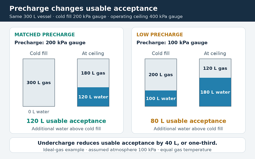
Original equilibrium gas-law example with atmospheric pressure assumed as 100 kPa. Water already present at cold fill consumes capacity; usable acceptance is the additional water admitted within the operating pressure window.
Verify the installation before adjusting it
An air-valve reading taken while water pressure remains applied generally reflects the coupled operating pressure, so it cannot establish the original precharge. A qualified technician should follow the vessel’s exact isolation, cooling, drainage and measurement instructions. Do not recharge a corroded, damaged or suspect vessel as an attempted repair.
Amtrol’s L-series instructions distinguish pre-fill checks from checks on an installed vessel and include special requirements for some higher precharge conditions. Those product-specific steps take precedence over a generic checklist. Keep an isolated vessel out of service only under a safe plant plan, and restore its required connection before normal operation.
Check for a shut isolation valve, blocked connection, failed separator, incorrect fill regulator setting or undocumented change to system water volume. Investigate why the charge was lost. Record the vessel condition, instrument used, water-side test condition, temperature and final verified setting.
Use the result to correct the right problem
Recalculate acceptance with the verified design pressures and the actual fluid expansion between credible cold and warm conditions, including shutdown warming for chilled-water systems. Use manufacturer properties for glycol mixtures. If precharge exceeds cold fill, the vessel can remain empty until system pressure reaches precharge; the compressed-at-cold-fill equation above no longer describes that initial interval.
Restore the approved setting only after confirming vessel integrity and the intended reserve convention. Then trend pressure over a controlled operating cycle and compare it with the accepted design envelope. A larger shell, a corrected charge and a repaired fill-control fault solve different problems; the measurements should determine which action is justified.
Sources and further reading
Continue your engineering workflow
For the wider design workflow, see the Chilled Water System Design Handbook.


Comments