Measuring Pump Head: Correct for Tap Elevation and Pipe Diameter
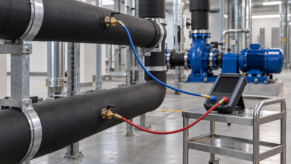
AI-generated editorial illustration; not a verified installation or construction detail.
A correct subtraction can still give the wrong head
A field report records 300 kPa gauge at pump suction and 460 kPa gauge at discharge. Dividing the 160 kPa difference by the weight density of water gives 16.34 m. That arithmetic is correct, but the reported pump head is incomplete if the discharge tap is higher and the discharge pipe has a smaller internal diameter.
This measurement check is useful when the observed duty appears to fall below the selected pump curve. Establish the actual pressure reference and measurement sections before concluding that the impeller, speed or pump condition is wrong.
Use the total-head equation at defined sections
KSB’s pump-head explanation expresses head through the energy added to the fluid. For steady incompressible flow, with the usual approximately uniform turbulent velocity-profile assumption, the total-head increase between suction section s and discharge section d is:
H = (pd − ps)/(ρg) + (zd − zs) + (vd² − vs²)/(2g).
Use pressure p in Pa, density ρ in kg/m³, gravitational acceleration g in m/s², elevation z in m and average velocity v in m/s. Every resulting term is in metres of pumped liquid. Gauge pressures may be subtracted when they share the same atmospheric reference; do not mix a gauge reading with an absolute reading.
Define each elevation at its pressure measurement point consistently with the selected section. Use actual internal bore for velocity, not nominal DN alone. If taps are remote from the pump flanges, the measured head increase also reflects intervening losses; comparing directly with a flange-to-flange pump curve then needs an additional boundary correction.
The distinction from system fill pressure is covered in Nexora’s fill-pressure and pump differential-head guide. Here the task is correcting a local field measurement.
Record the example inputs before calculating
Assume water density 998 kg/m³, g = 9.81 m/s² and measured pump flow of 18.0 L/s, or 0.0180 m³/s. Treat the readings as local static pressures already corrected to their tapping points. Ignore losses between these idealized measurement sections and the pump flanges for this worked example.
The suction pressure is 300.0 kPa gauge. Its section has a 150 mm internal bore and elevation zs = 0.0 m. The discharge pressure is 460.0 kPa gauge, its internal bore is 100 mm, and its elevation is zd = 1.20 m. The chosen zero elevation is arbitrary; only the difference matters.
For a circular section, area A = πD²/4 and velocity v = Q/A. Suction area is 0.017671 m², giving vs = 1.019 m/s. Discharge area is 0.007854 m², giving vd = 2.292 m/s. The same flow produces a higher velocity in the smaller discharge bore.
Add the three head terms with their signs
Pressure-head increase = (460,000 − 300,000)/(998 × 9.81) = 16.3426 m.
Elevation-head increase = 1.20 − 0.00 = +1.2000 m. Velocity-head increase = (2.2918² − 1.0186²)/(2 × 9.81) = +0.2148 m.
Total measured head increase = 16.3426 + 1.2000 + 0.2148 = 17.7574 m, or 17.76 m when rounded.
The pressure-only result understated this example by 1.4148 m, about 8.0% of the corrected value. That is enough to affect a preliminary comparison with a selection curve. It is not evidence that every site measurement has an 8% error.
The signs follow the actual geometry. A lower discharge tap gives a negative elevation term. A larger discharge bore may give a negative velocity term. Equal tap elevations and equal velocities make both corrections disappear. Keep the signed terms visible rather than using an unexplained absolute “correction allowance.”

Pressure head 16.3426 m + elevation head 1.2000 m + velocity-head correction 0.2148 m = 17.7574 m. These inputs are local tap pressures; a common-height liquid-filled DP connection needs the separate interpretation explained below.
Do not add elevation twice with a common-height instrument
A handheld differential-pressure instrument may connect to both taps through liquid-filled hoses, with its two sensing ports at the same elevation. Hydrostatic pressure in those hoses changes what the instrument receives. WIKA’s pressure-measurement handbook explains the elevation effect when an instrument is above or below its tapping point.
With both hoses completely filled by liquid of the same density as the process water, and no compensation already applied, the raw common-height differential becomes (pd − ps) + ρg(zd − zs). For this example it is 160.000 + 11.7485 = 171.7485 kPa.
Dividing that raw reading by ρg already includes the 1.20 m elevation contribution. Add only the 0.2148 m velocity correction to obtain the same 17.7574 m total. Adding another 1.20 m would overstate head.
This shortcut requires its stated conditions. Electronic subtraction of two local sensors is different. Unequal hose-fluid densities, gas pockets, remote seals and configured zero or elevation compensation require the instrument-specific model. Record whether the displayed value represents pressures at the taps or pressures at the sensor ports.
Make measurement quality visible in the report
The Yokogawa pressure-transmitter manual discusses accurate pressure transmission through impulse piping, including keeping liquid-service lines free of trapped gas. Follow the actual instrument manufacturer’s setup and connection instructions; the pump-head calculation cannot repair a blocked tap or unreliable sensing path.
Record simultaneous pressure and flow readings once speed and valve positions are stable. Where two separate gauges are used, document their ranges and uncertainties. Two instruments each specified at ±0.5% of a 1,000 kPa full scale can contribute a worst-case subtraction error of ±10 kPa, equivalent to about ±1.02 m here, before other uncertainties are included.
A suitably rated differential instrument may improve a small-difference measurement, but its differential range, static-pressure rating, temperature limits and hose ratings must all suit the service. Decimal places on the display do not establish accuracy.
Compare like with like before diagnosing the pump
Plot the corrected head with the measured flow on the curve for the installed impeller and actual rotational speed. Confirm the curve’s fluid and reference conditions. VFD frequency alone may not establish exact shaft speed where the drive and motor arrangement introduce a difference.
If the taps include a strainer, check valve or appreciable pipe length outside the pump flanges, document and estimate those losses at the measured flow before judging the pump. Do not silently remove a loss already included in the reference boundary.
Head alone does not diagnose suction reliability. Use Nexora’s NPSH check for chilled-water pumps for that separate assessment. Likewise, required remote-coil flow still needs verification even when the pump matches its curve.
Field measurement checklist
Mark both taps, pipe bores, elevations and the intended comparison boundary.
Identify local sensors versus remote liquid-filled lines and any existing compensation.
Confirm instrument condition, pressure and temperature ratings, calibration and uncertainty.
Capture steady pressure, flow, fluid condition and speed together.
Calculate signed pressure, elevation and velocity terms without double correction.
Compare with the correct curve and retain the original readings alongside the corrected result.
Use trained personnel and the site’s approved connection and isolation procedure. Do not open a pressurized fitting, defeat a protective interlock or approach unguarded rotating equipment to obtain a reading. The final report should make the measurement reproducible without making the work unsafe.
Related learning resource
Use a repeatable site record to retain the readings and their basis. Nexora’s HVAC Maintenance Checklist Pack is a related maintenance resource; add the actual tap locations, instrument arrangement and correction calculation required for your installation.
Sources and further reading
Engineering education only. Verify project conditions, applicable requirements and manufacturer data; use qualified professional judgment before design, selection, operation or maintenance decisions.


Comments