Minimum Outdoor Air at VAV Turndown: Prove the Flow, Not the Damper Position

AI-generated editorial illustration; not a verified installation or construction detail.
The low-airflow condition needs its own proof
A VAV air handler passes its design-airflow test with the outdoor damper at 25%. Months later, supply airflow is much lower, the damper still reads 25%, and everyone assumes ventilation is unchanged. That assumption skips the variable that moves the air: the pressure difference across the intake path.
This article treats the required outdoor-air setpoint as an approved design input. The task is to prove delivery while the AHU turns down, then check that the control and instruments can repeat that result. For the wider system arrangement, start with Nexora’s VAV system design guide.
Separate three values on the controls graphic
Damper position is an actuator command or measured shaft position. Outdoor airflow is a volume or mass rate. Outdoor-air fraction is outdoor airflow divided by total supply airflow on a consistent basis. None of these values can simply replace another. A 25% command does not establish either 25% free area or 25% outdoor air.
Trane’s single-zone VAV guidance explains how changing fan operation affects intake airflow and discusses damper-position scheduling and direct flow control. Its physical explanation remains useful, but its historical code references should not be treated as the edition governing a current project.
Position feedback also needs interpretation. A reported actuator angle cannot prove that the damper linkage is intact, blades are moving together or a weather louver is clear. Establish the physical arrangement before interpreting the trend.
Original example: the same opening delivers half the air
Assume an occupied AHU has an approved outdoor-air requirement of 1.20 m³/s. Supply airflow is 8.00 m³/s at design and 3.00 m³/s during the test at turndown. Occupancy and the approved outdoor-air setpoint remain unchanged. All airflow quantities use the same density reference; this is an intake-delivery example, not a multizone ventilation calculation.
At design flow, measured outdoor air is 1.20 m³/s and the pressure difference across a fixed intake path is 80 Pa. At turndown, assume that pressure difference becomes 20 Pa with the same damper opening. For this illustrative fixed resistance, take airflow proportional to the square root of pressure difference, with unchanged density and flow coefficient.
Estimated outdoor airflow at turndown = 1.20 × √(20 ÷ 80) = 0.60 m³/s. That is 600 L/s delivered against a 1,200 L/s requirement: a 600 L/s shortfall, or 50%. These assumed pressure readings describe the selected intake path, not the supply-duct static-pressure sensor.
At design, the outdoor-air fraction was 1.20 ÷ 8.00 = 15%. At turndown, the required fraction is 1.20 ÷ 3.00 = 40%. Yet the estimated delivered fraction is only 0.60 ÷ 3.00 = 20%. The fraction has increased while the actual outdoor airflow has halved.
Do not infer a new damper command from these ratios. Damper characteristics and interaction with return and relief paths are nonlinear. The calculation identifies a plausible failure mechanism; field measurement determines the actual delivery. Wind, stack effect, leakage and density changes can also alter the relationship.
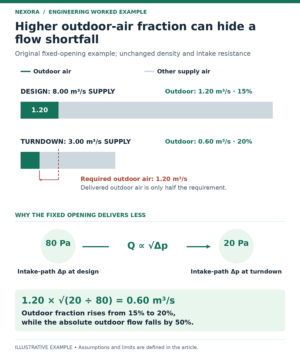
Original example: 1.20 × √(20 ÷ 80) = 0.60 m³/s. The required occupied outdoor flow remains 1.20 m³/s. These pressure drops are across the fixed intake path, not a duct-static setpoint or sensor velocity pressure.
Select the measurement for the minimum you must prove
Suppose the measurement-plane area is 2.40 m². At the required 1.20 m³/s, mean velocity is 1.20 ÷ 2.40 = 0.50 m/s. At the deficient 0.60 m³/s, it is 0.25 m/s. An instrument selected only around the maximum economizer airflow may perform poorly at these low velocities.
For air density of 1.20 kg/m³, velocity pressure is 0.5 × density × velocity². It is just 0.150 Pa at 0.50 m/s and 0.0375 Pa at 0.25 m/s. Those values are velocity pressures at the measurement plane, not the 80 Pa and 20 Pa intake-path losses in the previous example. Probe coefficients and instrument specifications determine the actual sensor signal.
EBTRON’s probe-placement guide distinguishes installed accuracy from laboratory sensor accuracy and addresses louver turbulence, damper interaction and close-coupled outdoor intakes. Its placement limits apply to its specified products. Use the installed model’s guidance rather than transferring one vendor’s spacing or minimum velocity to every technology.
Check the measurement range, zero behavior, density compensation and uncertainty at the minimum operating flow. A handheld reading at one convenient spot in a turbulent intake is not an adequate reference for recalibrating a multi-point station. When a suitable reference plane is unavailable, document that limitation and involve the instrument supplier and TAB specialist.
Choose a control approach that matches the arrangement
The ASHRAE controls handbook describes several approaches: an outdoor airflow station with modulating dampers, a measured outdoor-air injection system, or a calibrated pressure relationship across a suitable fixed opening. Which approach fits depends on the intake geometry, return arrangement and approved sequence.
Direct measurement is useful only if the controller has effective authority and a trustworthy signal. Trend setpoint, measured flow, output and actual response together. A controller held at its maximum output while airflow remains low needs investigation of the air path and available pressure, rather than more aggressive tuning.
A scheduled damper position versus fan speed can be checked at multiple operating points, but its repeatability must be demonstrated under the relevant conditions. Do not assume a successful design-speed balance proves the entire schedule. Keep minimum ventilation active when economizing is disabled; Nexora’s humid-weather economizer article covers that separate enable decision.
Run an occupied-mode test with clear acceptance criteria
Obtain the approved ventilation calculation, sequence revision, occupied schedule, minimum supply airflow and intended outdoor-air reset logic. Confirm which conditions the test represents.
Verify damper travel, intake cleanliness, sensor installation, units and calibration records. Record instrument identity and measurement uncertainty.
Test design, intermediate and minimum occupied supply airflow. At each stable point, record simultaneous outdoor flow, supply flow, damper command and feedback, fan operation and relevant pressure readings.
Include normal return or relief fan operation, exhaust loads and building-pressure behavior. Note unusual wind or door conditions rather than silently treating them as typical.
Compare measured outdoor flow with the approved setpoint and the project’s acceptance criteria. Investigate borderline results against uncertainty. Do not adopt an arbitrary tolerance from this example.
Remove authorized test overrides, restore the approved sequence and retain a trend demonstrating stable automatic operation. Do not defeat fire/smoke, low-temperature or equipment interlocks to obtain a passing number.
Verify the intake and the zones as separate acceptance checks
For a multizone system, adequate AHU intake alone does not prove that every occupied zone receives its required ventilation. Terminal minimums, air distribution and the approved system ventilation calculation still matter. Occupancy-based reset may legitimately change the intake setpoint; that change needs a documented basis rather than an assumption that cooling load tracks people.
If testing shows a deficiency, document the operating condition, measured shortfall and likely constraint for the responsible designer. Any change to intake size, damper arrangement, fan operation or terminal minimums needs coordinated review. The finished record should explain what airflow was verified, where, with which instruments and across which operating range.
Related learning resource
Nexora’s Air Balancing (TAB) Toolkit provides an instrument register, AHU/fan records and a deficiency log for organizing the test evidence. Add the occupied operating state and outdoor-air setpoint to the site record, and set acceptance bands to the project specification.
Sources and further reading
Engineering education only. Verify project conditions, applicable requirements and manufacturer data; use qualified professional judgment before design, selection, operation or maintenance decisions.


Comments