Horizontal Water Tanks: Why Half the Level Change Is Not Half the Volume

A level indicator reports a height. A quantity report needs a volume. Those values are proportional in a vertical tank with a constant horizontal cross-section, but not in a horizontal circular cylinder. Near its bottom, a small rise wets a narrow strip. Near the centerline, the same rise spans almost the full diameter. Treating every millimetre as the same number of litres distorts the inventory.
The geometry below applies to a level, flat-ended horizontal cylinder with a uniform internal circular cross-section. It is a quantity calculation only. The two example levels are declared analysis boundaries, not recommended operating limits or a basis for selecting reserve capacity.
1. Define height, diameter and internal length
Let r be internal radius, L be internal cylindrical length, and h be liquid height measured vertically upward from the internal bottom. The permitted geometric range is 0 ≤ h ≤ 2r. Use internal dimensions consistently; outside dimensions include material that does not hold water.
The full cylinder volume is πr²L. At h = r, the cylinder is exactly half full by symmetry. However, that midpoint fact does not make the whole level-volume relationship linear. A quarter of the diameter is not a quarter of the capacity, and a three-quarter level is not three-quarter capacity.
The Endress+Hauser Prosonic S instructions describe a horizontal-cylinder linearization that converts level to volume and distinguish it from table-based conversion. The stated geometry option excludes domed ends. This is an important boundary: tank shape must be established before applying a simple conversion. No instrument adjustments are needed to follow this offline example.
2. Calculate the circular segment
At any height h, the filled end-section is a circular segment. Its area is A(h) = r² arccos((r − h)/r) − (r − h)√(2rh − h²). Filled volume is V(h) = L × A(h). Evaluate arccos in radians. With lengths in metres, area is in square metres and volume is in cubic metres.
The equation combines a circular sector with a triangular correction. Below the centerline, the correction subtracts the triangular portion outside the filled segment. Above the centerline, r − h becomes negative and the same formula continues to give the correct larger area. Do not replace that signed term with its absolute value.
Before calculating project quantities, test the equation at three known points: V(0) = 0, V(r) = πr²L/2, and V(2r) = πr²L. A spreadsheet returning a nonzero empty volume or the wrong midpoint is not ready for use. These checks catch degree-mode trigonometry and misplaced parentheses quickly.
3. Work the two endpoint volumes
Assume a hypothetical flat-ended tank with internal radius 1.00 m and internal cylindrical length 3.00 m. Its internal diameter is 2.00 m and its gross geometric capacity is π × 1² × 3 = 9.424778 m³. Consider the quantity between a lower level of 0.50 m and an upper level of 1.50 m.
At h = 0.50 m, arccos((1 − 0.50)/1) = arccos(0.5) = 1.047198 radians. The square-root term is √(2 × 1 × 0.50 − 0.50²) = √0.75 = 0.866025 m. Segment area is 1.047198 − 0.50 × 0.866025 = 0.614185 m². Multiplying by 3 m gives V-low = 1.842555 m³.
At h = 1.50 m, symmetry provides an independent check: the unfilled top segment has the same area as the filled bottom segment at 0.50 m. Therefore V-high = 9.424778 − 1.842555 = 7.582223 m³. Direct substitution into the equation gives the same result.
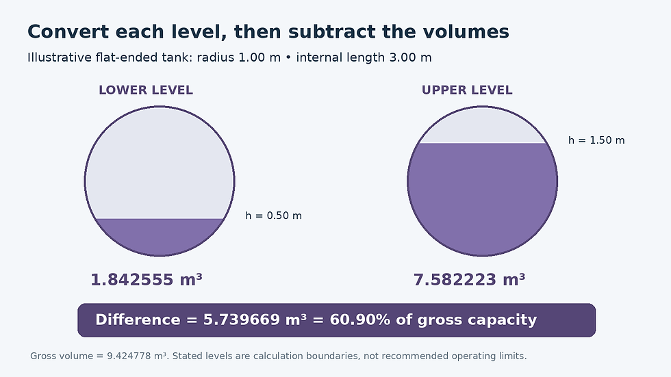
Original circular-segment calculation for r = 1 m and L = 3 m. Half the diameter band contains 60.90% of gross geometric volume.
The volume between the two stated levels is 7.582223 − 1.842555 = 5.739669 m³, approximately 5,740 L. That is 60.90% of gross capacity, even though the 1.00 m height band spans exactly half the 2.00 m diameter. Here “between levels” means the geometric difference only; actual availability requires a separately defined operating context.
4. Compare the linear shortcut with the geometry
A linear conversion would assign 25% capacity to h = 0.50 m and 75% capacity to h = 1.50 m. It would therefore report a band volume of 50% × 9.424778 = 4.712389 m³. That understates the calculated central-band quantity by 1.027280 m³, or 17.90% relative to the geometric band volume.
The correct lower endpoint is 19.55% of capacity, while the upper endpoint is 80.45%. The equal deviations around half full are a useful visual check for this symmetric cylinder. They also explain why a nearly correct reading at the midpoint cannot validate a straight-line conversion everywhere else.
Always convert both endpoint heights separately and subtract the resulting volumes. Multiplying the height difference by gross capacity divided by diameter assumes constant horizontal area, which this shape does not have. A correctly calculated volume at one endpoint does not eliminate the need to calculate the other.
5. Understand how level uncertainty affects quantity
The local rate of volume change with height is dV/dh = 2L√(2rh − h²). At the example centerline, this becomes 2 × 3 × 1 = 6 m². A small 10 mm level change near that location corresponds to approximately 6 × 0.010 = 0.060 m³, or 60 L.
At h = 0.50 m, the local rate is about 5.196 m², giving approximately 52 L per 10 mm. These are local linear approximations, not a replacement for the segment equation over a large height change. They show why a stated level uncertainty cannot be converted to one universal volume uncertainty for the entire tank.
Dimension uncertainty matters too. A radius or length taken from an unverified drawing adds uncertainty beyond the level reading. Reporting many calculated decimal places does not remove those limitations. Preserve full precision in calculations and round the final quantity to match the evidence.
6. Prefer a verified tank-specific relationship
Confirm orientation, internal dimensions and the reference point for the reported height.
Establish whether the reading is height from the bottom or distance down from another datum.
Identify domed ends, noncircular geometry, tilt and internal displacement before choosing a model.
Prefer a verified manufacturer strapping table when it represents the actual tank more faithfully.
Check table units, endpoints and interpolation assumptions before using intermediate values.
Label gross capacity and the quantity between stated levels as separate results.
The practical rule is straightforward: establish the geometry, convert each level to volume, then subtract. For a horizontal cylinder, the central height band holds disproportionately more water. A traceable level-volume relationship makes that effect visible instead of burying it inside a misleading percentage.


Comments