Variable-Flow Chillers: Commission the Flow Ramp During Staging
Treat the transition as its own operating condition
A plant can meet every steady-state evaporator flow requirement and still trip when a second chiller enters service. Opening another parallel branch changes the flow through the running machine before the new compressor starts. Commissioning must establish how quickly that redistribution occurs and whether the running chiller can unload safely.
This article addresses the hydraulic transition after a staging decision has been made. Use a manufacturer-approved sequence for the actual piping arrangement, chiller controls, pumps and valves. Maintain all native freeze, pressure and proof-of-flow protections throughout testing.
Obtain three separate limits
For each selected evaporator, record minimum flow, maximum flow and permitted rate of flow change. Ask whether the rate is based on design flow, initial flow or instantaneous flow; whether rising and falling limits differ; and which averaging window, temperature-control tolerance and operating conditions apply. A percentage without its denominator is incomplete.
Manufacturer capabilities differ. Trane’s CGAM catalog associates one flow-change rate with a stated leaving-water control tolerance and discusses a higher tolerated rate subject to minimum flow. Daikin’s Magnitude WMT engineering data gives a different rate limit. Neither publication supplies a universal setting for other machines.
Use the project-approved selection and current unit documentation to resolve the limit. Keep the original wording in the commissioning record alongside its engineering interpretation. VFD acceleration time and isolation-valve stroke time describe actuators; neither directly demonstrates the water-flow ramp through an evaporator.
Calculate an initial transition envelope
Assume an illustrative chiller has 40 L/s design flow, 20 L/s minimum flow and 48 L/s maximum flow. For this example only, the approved falling-flow limit is explicitly 10% of design flow per minute, equivalent to 4.0 L/s per minute. These are assumed project inputs, not recommendations for a particular product.
Chiller A initially receives 40 L/s. The intended two-chiller condition is 24 L/s through A and 24 L/s through B, totaling 48 L/s. A must lose 16 L/s while remaining above its 20 L/s minimum. The shortest ideal uniform ramp is 16/4 = 4.0 minutes. A 60-second redistribution would be 16 L/s per minute, or 40% of design flow per minute, four times the assumed limit.
A five-minute uniform ramp for A would average 3.2 L/s per minute, or 8% of design flow per minute. That provides arithmetic headroom, but commissioning must still check local peaks, sensor delay and interacting controls. The new branch’s startup flow proof, preflow dwell and subsequent ramp requirements remain separate acceptance conditions.
This calculation establishes a lower-bound planning time. It does not prove that a four-minute valve stroke produces a four-minute flow ramp. Installed valve characteristic, differential pressure and pump response determine the actual relationship. Trane’s VPF engineering newsletter specifically treats isolation-valve transients and coordinated unloading as design issues.
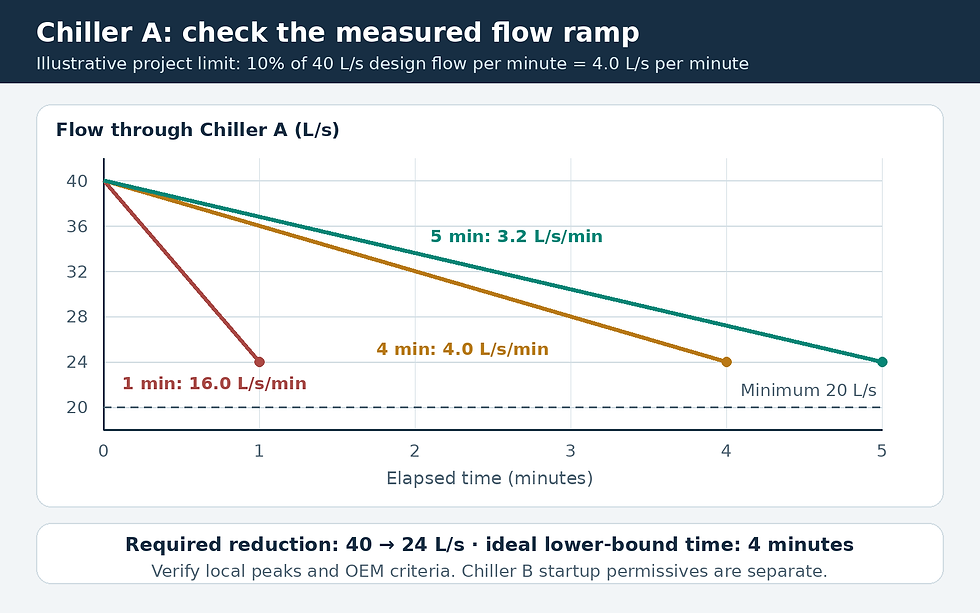
Original ramp-envelope example for the running chiller. The four-minute line is an ideal planning lower bound, not a complete valve or Chiller B startup sequence.
Measure each branch through the event
Trend A and B evaporator flow, valve commands and feedback, pump speed, relevant differential pressure, bypass position, compressor loading, entering and leaving water temperatures, and flow-proven status. Total header flow can increase while A’s flow falls sharply. Branch measurements reveal that redistribution.
Choose synchronized logging faster than the expected transition and document instrument update rates. A five-minute trend interval cannot characterize a one-minute event. If the approved test interprets the limit as a continuous ramp ceiling, a 15-second diagnostic interval allows a 1.0 L/s change at 4.0 L/s per minute. A measured fall from 40.0 to 38.6 L/s in that interval is 5.6 L/s per minute, or 14% of design flow per minute.
The short-interval calculation is a diagnostic example. Agree the compliance window with the manufacturer before declaring a failure. Filtering can suppress noise while hiding a real transient, so retain raw points and assess both sensor uncertainty and filter delay.
Coordinate the valves, pumps and compressor capacity
Before opening B’s branch, verify available pumping capacity, bypass authority and the permitted operating envelope for A. Where required by the approved sequence, unload A before redistribution. Coordinate pump response and valve movement using measured branch flow rather than assuming equal division between parallel evaporators.
Establish B’s required flow and complete its startup permissives before enabling refrigeration. Account for temporary supply-temperature dilution while water passes through an idle evaporator, and for warmer supply caused by unloading A. Process cooling may have tighter limits than comfort cooling. The permitted supply-temperature excursion belongs in the acceptance criteria.
During a staging-down test, unload and stop the outgoing chiller in the required order, maintain its specified postflow, and then close its branch under the approved sequence. Verify the surviving chiller’s rising-flow limit and maximum flow. Minimum bypass control, network delays and interacting differential-pressure loops also require functional checks; Trane’s chilled-water design review illustrates the importance of controllable bypass sizing and adequate loop volume.
Define a pass that can be reproduced
Accept the transition only when each operating chiller remains within its approved flow envelope, rate limits and temperature-control criteria, with all required permissives and no protective trips. Repeat at representative low-flow and high-demand conditions, including unequal branch resistance where applicable.
If the test fails, hold or reverse the transition only through the approved recovery sequence. Investigate valve authority, measurement quality, control lag and unloading response before changing limits. Save plots, control revisions and the exact tested conditions so the next service team can reproduce the result.
Sources and further reading
Continue your engineering workflow
For the wider design workflow, see the Chilled Water System Design Handbook.


Comments