BMS I/O Takeoff: Separate Wired Points, Network Values and Spare Capacity

Original illustrative engineering schematic. The worked calculation below uses explicit example inputs.
A building-management-system estimate often begins with a total number of points. That number is useful only after its meaning is clear. A hardwired temperature input, a value read from a packaged chiller and a calculated software value do not create the same hardware requirement. Combining them into one total and dividing by controller capacity can produce a plausible-looking but unbuildable bill of quantities.
The original example below reconciles a small controls package from data items to physical channels and controller assemblies. All hardware capacities and spare requirements are illustrative. It is not a controls design, product selection or wiring instruction. The approved sequence, equipment interfaces, manufacturer compatibility and project security requirements remain controlling inputs.
1. Give every scheduled point an interface classification
Wired analog input, or AI: a physical input channel for the specified sensor signal. Record the actual signal, not just the word analog.
Wired digital input, or DI: a physical input for a defined contact or other compatible discrete signal. Some manufacturers use binary input, BI.
Wired analog output, or AO, and digital output, or DO: physical output channels with the required electrical characteristics. Binary output, BO, is another common term.
Network value: an agreed item obtained through a communications interface. It may need integration and licensing work without consuming a new local hardwired channel.
Software value: a defined calculation, setpoint or other internally maintained value. It belongs in the software scope, not automatically in the field-terminal count.
BACnet represents information using objects and properties, including inputs, outputs, values and schedules. The committee-hosted explanation illustrates why an application-level point count is not a terminal schedule. Do not infer a physical wire merely from an object label; establish where the underlying signal originates and how it reaches the controller in the proposed architecture.
2. Reconcile the example package without losing integration scope
Assume four AHUs each have a local field controller. Each AHU needs five AI, four DI, three AO and two DO in the reviewed hardwired schedule. In addition, eight agreed values per AHU arrive from networked drives. Two packaged chillers each provide twelve network values, with their factory controls included in the chiller package. Twelve further values are created in the supervisory software.
Wired channels per AHU = 5 + 4 + 3 + 2 = 14.
Four-AHU wired totals: AI 20; DI 16; AO 12; DO 8; total 56.
Network values = (4 × 8) + (2 × 12) = 56.
Software values = 12.
Scheduled data items in this defined register = 56 + 56 + 12 = 124.
The 124 total is a register reconciliation, not an instruction to buy 124 physical channels or a statement of software licence consumption. Manufacturer licensing may count devices, objects, points or other resources differently. Nor does 56 wired channels mean 56 separate field devices: one drive can have a wired enable, a wired status and several networked readings. Keep the device register, signal register and software scope linked but separate.
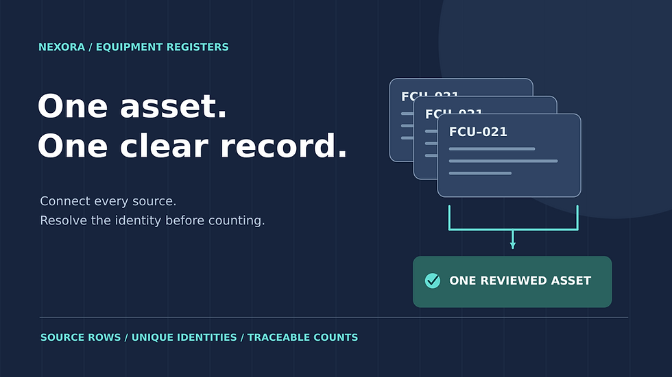
Start from reviewed asset identities so one AHU shown in a controls drawing and an equipment schedule does not become two controllers. Nexora’s equipment-register workflow explains the difference between repeated source rows and real additional assets.

Illustrative final per-controller channels are AI 8, DI 6, AO 4 and DO 4, with 5, 4, 3 and 2 respectively used. Remaining capacity is 37.5%, 33.3%, 25% and 50% of installed channels. Fictional capacities; actual signal types and module compatibility require project review.
3. Define the denominator of the spare requirement
For this teaching case only, assume the specification requires at least 20% of the installed usable channels to remain spare in each signal class at every local controller. This is not a universal industry percentage. A clause requiring 20% extra channels above connected demand uses a different denominator. Resolve ambiguous wording before applying a formula.
Let U = used channels, C = installed usable channels and r = required spare fraction of installed capacity.
(C − U) ÷ C ≥ r, so C ≥ U ÷ (1 − r).
Minimum whole-channel capacity = ceiling[U ÷ (1 − r)].
For one AHU at r = 0.20:
AI: ceiling(5 ÷ 0.8) = 7.
DI: ceiling(4 ÷ 0.8) = 5.
AO: ceiling(3 ÷ 0.8) = 4.
DO: ceiling(2 ÷ 0.8) = 3.
For example, adding 20% to five used AI gives six installed channels, but only one of six is spare: 16.7%, not 20%. The two definitions agree neither algebraically nor after rounding. Record both the requirement wording and the calculation used, including whether spare channels must be fitted and usable or only capable of future installation.
4. Test real channel classes, not the headline controller size
Consider a fictional base controller offering six AI, six DI, four AO and two DO. It has eighteen channels overall, of which fourteen are used. An aggregate calculation reports four spare channels, or 22.2%, and appears to satisfy the example requirement. It fails, however, because AI spare capacity is only 1/6 = 16.7% and DO spare capacity is zero.
Assume a compatible hypothetical expansion module adds two AI and two DO to each local controller, with all power, enclosure, communications and application limits separately checked. The final local capacities are eight AI, six DI, four AO and four DO. The original fourteen connected signals remain unchanged; the module adds installed capacity, not demand.
Per-controller spare fractions after expansion:
AI = (8 − 5) ÷ 8 = 37.5%.
DI = (6 − 4) ÷ 6 = 33.3%.
AO = (4 − 3) ÷ 4 = 25.0%.
DO = (4 − 2) ÷ 4 = 50.0%.
Package hardware: 4 base controllers + 4 expansion modules.
Installed channels = 4 × (8 + 6 + 4 + 4) = 88.
Used channels = 56; spare channels = 32.
The module is not selected merely because its total capacity is four. Each additional channel must support the required signal class. Johnson Controls’ published CV specifications, for example, distinguish universal inputs, configurable outputs and binary outputs, with defined electrical modes. This demonstrates why a configurable channel cannot be counted simultaneously as a spare analog output and a spare digital output.
5. Keep spare capacity local and integration obligations visible
Unused channels at AHU-01 do not automatically satisfy a requirement at AHU-04. Cable routes, segregation, control autonomy, panel boundaries and the approved architecture can prevent pooling. Evaluate each controller first, then sum the hardware quantities. Also distinguish an empty expansion slot from an installed usable channel; they are different deliverables unless the specification explicitly treats them as equivalent.
Network integration needs its own line items: the required interface or gateway, communications infrastructure, approved data mapping, graphics, alarms, trends, command permissions and testing. The BACnet Committee describes the manufacturer’s PICS as a statement of implemented protocol capabilities. Review it together with the project-specific point list and interface agreement; a protocol badge alone does not establish that every required value or command is available.
Do not remove a required wired interlock simply because a similar status appears on the network. Likewise, do not add another sensor because its value appears on two graphics. Resolve the approved physical and functional boundary with the responsible designer. Safety-related or regulated interfaces require their own approved arrangements and are not redesigned by this counting exercise.
6. Release three reconciled schedules
Field schedule: each device, signal type, actual electrical characteristics, cable destination and physical channel assignment.
Hardware schedule: each controller and module, used and usable channels by class, spare calculation, power and enclosure checks, and manufacturer compatibility evidence.
Integration schedule: source device, agreed value or command, interface responsibility, software deliverable and verification requirement.
For unresolved point ownership, network availability or spare-capacity wording, issue a precise technical clarification instead of hiding an allowance in the total. The HVAC RFI Pack provides a register, form, tracker, dashboard and HVAC question library that includes BMS interfaces. It can organize those decisions; it is not an I/O design engine or a substitute for the approved point schedule.
Continue the calculation review
Sources and calculation basis
Primary references checked on 23 October 2026. The worked examples and diagrams are original illustrative calculations, not manufacturer selections or project approvals. Apply the stated limitations and the requirements governing the actual project.

Comments