Car Park Gas Detection: A Normal-Mode Ventilation Commissioning Checklist
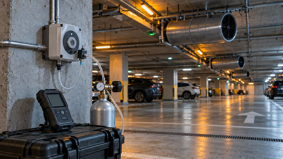
Commission normal-mode car park gas detection by proving the complete chain: the correct sensor detects the intended gas, the controller interprets a valid signal, the assigned zone requests the approved ventilation response and the equipment delivers the required airflow. Record the result at each link. A green controller display or an illuminated fan icon is only one observation.
This article provides an original test-planning checklist for qualified commissioning teams. It does not prescribe gas thresholds, sensor spacing, ventilation rates or a fire sequence. Those decisions belong in the approved project design, applicable requirements and equipment instructions. Gas challenges and fault tests require a controlled method, trained personnel and protection for occupants throughout.
1. Freeze the approved normal-mode sequence
Prepare a signed cause-and-effect schedule before testing. Define which pollutants the design monitors, the sensors assigned to each zone and the logic used when more than one sensor or zone calls for ventilation. Record whether a stage uses an instantaneous reading, an average or another approved evaluation method. These distinctions affect both the stimulus and the observation period.
Identify each sensor by physical location, equipment tag, gas type, range, address and controller input.
Record each stage’s activation setpoint, reset value or hysteresis, units, evaluation interval and intentional delay.
Record minimum ventilation, fan stages or speed commands, damper positions and any approved run-on time.
Define alarm destinations, latching and reset behavior, fault response, communication-loss response and recovery after power restoration.
Identify the drawing, software revision and person responsible for accepting every expected result.
Manufacturer features demonstrate why a generic sequence is inadequate. The Macurco DVP-120 manual describes configurable zones, rising/falling concentrations, timing and independent ventilation/alarm functions. Its behavior is specific to that controller and configuration; it should not be copied unchanged into another system.
2. Establish what each test actually proves
Separate sensor-response verification, signal-path verification and ventilation-performance verification in the record. A manufacturer-approved gas challenge checks the sensing element’s response to the intended gas under controlled conditions. Calibration is a separate adjustment or verification process performed as the relevant instructions require. A controller simulation can establish mapping and logic while leaving the sensing element untested.
Read the limitations of built-in test modes before using them. Honeywell’s E3Point standalone manual states that its TestMode activates outputs but does not detect gas during that procedure. Such a function therefore needs an approved commissioning method that maintains protection; it cannot establish an end-to-end gas-response pass by itself.
Use the correct certified test gas, delivery equipment and application method for the exact detector. Record cylinder identity, concentration, expiry, detector identification, initial condition and response. Do not use vehicle exhaust as a calibration source or release gas into occupied areas to create an uncontrolled challenge. Macurco’s CM-6 instructions illustrate why gas testing, alarm testing and loop testing are distinct manufacturer procedures.
3. Use a cause-and-effect test matrix
The following is an original matrix structure for a hypothetical two-zone installation, Z1 and Z2. S1 and S2 mean the project-approved first and second activation setpoints; R1 and R2 mean their approved reset values. They are placeholders, not recommended concentrations. Add the specified timing and the expected equipment tags before execution.
Baseline: establish valid readings below applicable reset conditions. Expect the approved minimum normal-mode state. Record sensor validity, controller state, fan/damper commands and measured airflow.
Z1 first stage: challenge an assigned sensor using the approved method to meet S1 and its evaluation/delay conditions. Confirm only the equipment required by the approved zone matrix responds.
Z1 higher stage: meet the approved S2 condition. Verify escalation, local indications and remote alarms independently, including their timestamps and any required operator notification.
Z2 first stage: repeat with a Z2 sensor. Verify physical sensor identity against the controller address and served fans; do not accept a correct response from the wrong zone.
Concurrent demand: establish calls from both zones using approved test methods. Release one call. Confirm shared equipment remains in the state required by the remaining demand.
Falling concentration: pass the approved reset values and run-on conditions. Confirm staged recovery and any manual reset requirement; record actual elapsed times.
Sensor or communication fault: apply the manufacturer-approved fault simulation. Confirm the correct point becomes invalid, a fault is annunciated and the documented ventilation fallback is achieved.
Equipment failure: test the approved fan/damper failure scenario. Confirm that a command without the required proof produces the documented alarm and response.
Restoration: follow the approved recovery test. Verify startup/warm-up status, retained configuration, valid sensing, automatic operation and removal of temporary test conditions.

Original normal-mode test framework. Setpoints, delays, fault responses and fire-mode priorities must come from the approved project sequence.
4. Treat an invalid signal as a distinct condition
A lost signal must not silently become a believable low gas concentration. Define how the controller distinguishes valid low readings from an open loop, a failed detector, stale network data and a powered-down device. Use the manufacturer’s signal definitions rather than assuming that the same analogue value or network flag means the same thing across products.
For example, the DVP-120 documentation identifies specific input faults and trouble indications. The commissioning decision is whether the installed system routes the detected fault to the approved recipients and produces the approved response. “Fail-safe” in a relay menu is not a complete statement of what the ventilation system will do during every failure.
Do not invent a universal full-speed fallback or accept a silent stop by default. Require the responsible designer to define the response for the actual arrangement, including shared plant and available backup power. If that decision is missing, record an unresolved design item and obtain it before acceptance.
5. Prove airflow beyond the control signal
Document what “fan proof” means at each point. A controller output, a contactor auxiliary contact, a drive-run status and an airflow measurement prove different things. Check the installed proof device and its delay against the approved sequence. Then verify air quantities and routes with the normal-mode ventilation equipment in the specified operating state.
Record relevant damper positions, makeup-air availability and the status of interacting fans. For jet-fan systems, include the project’s approved distribution and performance verification requirements. A successful control test does not by itself demonstrate pollutant dilution everywhere in the car park.
6. Keep the smoke/fire strategy separate
Normal pollutant control does not establish the smoke-control sequence, fire-mode fan duties, fire alarm priorities or emergency controls. Where equipment is shared, coordinate a separately approved integrated test with the responsible fire and controls specialists. Do not disable protective functions, modify fire logic or substitute the normal-mode matrix for the engineered fire strategy.
Close out with signed test sheets, calibrated-instrument details, trend evidence, an as-left configuration backup and a retest register for failures. Assign future inspection and calibration responsibilities using current manufacturer instructions and project requirements. Related reading: normal versus fire-mode operation and HVAC fan commissioning.
Continue your engineering workflow
For broader ventilation-system design guidance, explore the Nexora Ventilation Exhaust Design Practical Engineering Handbook. Get the complete handbook.


Comments