Chilled-Water Insulation: Vapor-Barrier Continuity at Supports, Valves and Penetrations
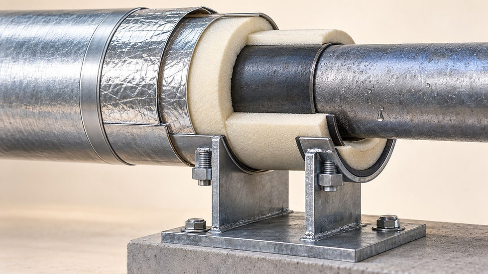
Chilled-water insulation needs continuous thermal protection and a continuous vapor-control system around the entire cold assembly. Supports, valve stems, removable covers and wall penetrations deserve individual details because a sound straight run does not prove these interfaces will remain dry. Review the connections between materials, inspect them before concealment, and then test surface temperatures against the local dew point during operation.
In specifications, “vapor barrier” often describes the overall protective layer. The selected system may instead use a rated vapor retarder or a closed-cell material with suitable vapor resistance. Use the manufacturer’s terminology and approved complete system, including its joints, adhesives and accessories.
1. Separate surface condensation from hidden moisture ingress
Surface condensation becomes possible when an exposed surface reaches the surrounding air’s dew point. Hidden moisture ingress is a different inspection problem: water vapor can reach colder regions through discontinuities even when the visible outer jacket looks dry. Thermal thickness and vapor continuity therefore need separate evidence. Johns Manville’s chilled-water guidance addresses both surface temperature and properly sealed vapor-retarder joints.
A protective metal jacket is not automatically the project’s vapor-control layer. Its fasteners, overlaps and weather seals have their own purposes. Identify exactly which layer resists vapor entry and how it crosses every detail. The Johns Manville metal-jacketing installation guide illustrates the separate insulation, vapor retarder, outer jacket and support components.
2. Worked dew-point check: one support can fail a dry-looking run
Assume a service corridor is at 30°C and 70% relative humidity while chilled water is operating at 6°C. For an illustrative dew-point calculation, use γ = ln(RH/100) + 17.62T/(243.12 + T), followed by Td = 243.12γ/(17.62 − γ), with temperatures in °C. This form is provided in Vaisala’s dew-point calculation documentation.
Substitution gives γ = 1.5787 and Td = 23.93°C. Suppose a suitable contact measurement finds 26.5°C on a straight insulated section and 20.0°C on exposed metal at a support. The straight section is 2.57 K above dew point. The support is 3.93 K below dew point, so condensation is expected there if the condition persists.
Now retain the same air temperature but increase relative humidity to 80%. Dew point rises to 26.17°C. If the straight-section surface temperature stayed at 26.5°C, its margin would be only 0.33 K. That sensitivity check demonstrates why a dry test on a mild day cannot establish performance for a more humid design condition.
These are invented readings, not insulation-sizing results. Surface temperature also depends on geometry, insulation condition, air movement and radiation. Measurement uncertainty matters when the margin is small. Set the project’s required allowance through its design criteria and selected insulation calculation method; do not adopt a universal temperature margin from this example.

Schematic inspection points, not construction details. Orange indicates the vapor-control boundary, green the insulation and blue the cold pipe or component. Use approved assembly details.
3. Supports: preserve load capacity, thickness and vapor continuity
At a support, review the mechanical load path and thermal path together. The approved insert or support assembly must carry the load without reducing the insulation below its required effective thickness. Check the interfaces between the insert and adjacent insulation, the underside hidden by the saddle, and any metal connection that reaches the cold pipe.
The Armacell application manual gives system-specific support details and stresses sealed bonds between insulation and support materials. Its methods should be used only with the products and conditions they cover; another insulation system needs its own approved detail.
Confirm the support insert matches the pipe size, insulation thickness, load and service conditions.
Inspect both end interfaces and the longitudinal closure before the saddle hides them.
Check for crushed insulation, open seams, exposed cold metal and damage from sharp edges.
Confirm the detail accommodates specified movement without tearing the seal.
Record a photograph from below as well as from the accessible side. A neat upper seam can coexist with an unsealed lower joint. If the installed hanger differs from the approved detail, resolve that mismatch before closing the ceiling.
4. Valves and removable covers: design for the next maintenance visit
Trace the cold boundary around the valve body, bonnet, flanges, test points and drain connections. Identify where insulation must terminate and how the termination is sealed. Keep actuators, operating parts, identification and service access available as required by the equipment manufacturer. Wrapping everything indiscriminately can create an access problem without producing a reliable seal.
For removable sections, require a detail showing how the vapor-control layer is restored after removal. A reusable cover needs an agreed joint and termination arrangement; closing its straps is not, by itself, proof of vapor continuity. Place the inspection point where the maintainer can actually see and reseal it.
As an acceptance exercise, have the maintenance team demonstrate access to one representative valve, then reinstall and inspect the assembly. Record the closure method and replacement materials in the handover instructions. This practical check exposes covers that can be installed once but cannot be reliably restored in the available space.
5. Penetrations: coordinate the complete assembly
At a wall or floor penetration, show the pipe, insulation, vapor-control layer, sleeve and required sealing system in one coordinated detail. Check whether the selected penetration assembly permits the proposed insulation to pass through and how any termination is completed. Rated barriers require the applicable tested or approved firestop arrangement; a convenient generic sealant is not a substitute.
Do not assume a firestop, acoustic seal or weather seal also provides the intended vapor resistance. Confirm compatibility and responsibilities at the interface. Look for insulation cut away to fit a sleeve, compressed material, inaccessible joints inside the opening and sealing products that prevent later inspection. Resolve these before the opening is closed.
6. Use a two-stage inspection and repair record
Before cooling operation, verify dry, clean substrate conditions and the approved installation procedure. Inspect material transitions and photograph concealed joints.
Before enclosure, map each support, removable section and penetration to its approved detail. Record defects by location and assign responsibility for correction.
During representative operation, measure local air temperature and relative humidity with suitable instruments. Calculate dew point and check suspect surface temperatures.
Treat thermal images as screening evidence. Shiny metal, viewing angle and emissivity can distort apparent temperatures; corroborate suspect results with a suitable measurement.
If moisture is present, investigate its extent and source before resealing. Follow the approved repair process for affected insulation, substrate and vapor-control layers.
Retest repaired details and record conditions, photographs and access requirements for future maintenance.
The deliverable is an inspectable, maintainable cold-surface enclosure. A dry outer surface during one visit does not establish that hidden insulation is dry or that the system will perform at the project’s maximum humidity condition.
For material selection background, see Chilled-Water Pipe Insulation: Types, Applications, Advantages and Disadvantages. Where movement affects supports and seals, see Chilled-Water Pipe Expansion: Anchors, Guides and Flexible Connections.
Continue your engineering workflow
For broader MEP piping-design guidance, explore the Nexora MEP Pipe Design and Sizing Handbook. Get the complete handbook.


Comments