Cooling-Coil Heat Balance: Reconciling Airside and Waterside Readings

Compare cooling-coil capacity on both sides of the same physical boundary, using synchronized measurements and consistent mass and enthalpy bases. For a wet coil, air loses both heat and moisture. The liquid leaving the drain carries a small amount of energy too. A difference between the two calculated capacities needs an uncertainty check before it supports a diagnosis.
1. Draw the measurement boundary first
Mark the entering and leaving air planes, chilled-water connections and condensate outlet on a sketch. Keep the supply fan, reheat coil and unrelated pipe branches outside the boundary. A leaving-air sensor downstream of a draw-through fan measures air after fan heat has been added; it cannot be used as the coil outlet without an appropriate correction.
State the test purpose. An energy balance checks whether two independently measured heat rates agree. A capacity acceptance test checks performance against the approved selection at specified conditions. Agreement between the two sides does not establish that the coil meets its scheduled duty.
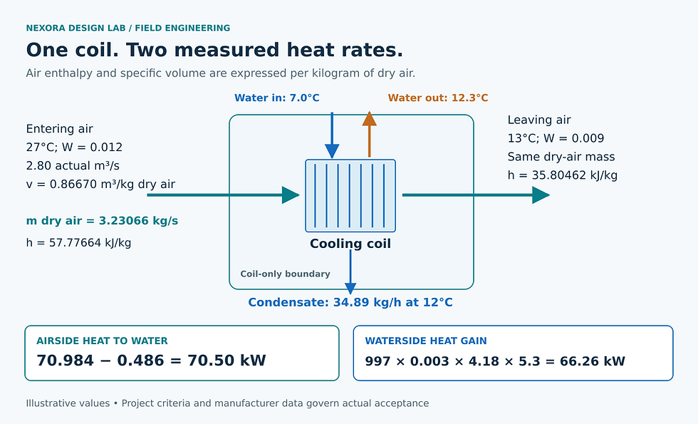
Illustrative steady-state balance: psychrometric enthalpy uses dry-air mass, and the liquid condensate energy leaves through a separate outlet. The 4.24 kW discrepancy requires an uncertainty assessment.
For this method, assume steady operation, negligible heat leakage through the enclosure, no air bypass outside the measured boundary, no water leakage, and negligible kinetic and potential energy changes. If those assumptions fail, add the missing terms or change the test arrangement. See AHU fan heat and coil-selection temperatures for the boundary issue.
2. Use dry-air mass with psychrometric enthalpy
Psychrometric humidity ratio W is kilograms of water vapor per kilogram of dry air. Enthalpy h and specific volume v are also commonly expressed per kilogram of dry air. Therefore, use dry-air mass flow, m_da = V_air/v, where V_air is actual volumetric airflow at the same state used to determine v. Do not multiply an enthalpy in kJ/kg dry air by a total moist-air mass flow. These property bases are defined in ASHRAE Fundamentals, Psychrometrics.
For the illustrative calculation below, use h = 1.006T + W(2501 + 1.86T), in kJ/kg dry air, and v = 0.287042(T + 273.15)(1 + 1.607858W)/p, in m³/kg dry air. Temperature T is °C and absolute pressure p is kPa. These ideal-gas approximations are suitable for this example; use a consistent validated property method in the project calculation.
With condensate leaving at temperature T_c, the airside heat transferred to the coolant is Q_air = m_da(h_in − h_out) − m_cond h_liquid, where m_cond = m_da(W_in − W_out). Use a liquid-water enthalpy referenced consistently with the moist-air equations; here h_liquid ≈ 4.18T_c kJ/kg. The subtraction follows the energy leaving through the drain. ASHRAE’s coil chapter, Section 8 includes this condensate term.
3. Work through one deliberately imperfect field snapshot
Assume measured entering airflow of 2.80 m³/s at 27°C, W_in = 0.012 kg/kg and 101.325 kPa. Leaving air is 13°C with W_out = 0.009 kg/kg. Condensate leaves at an assumed 12°C. These are invented test inputs, not manufacturer ratings; the humidity ratios are supplied rather than inferred from an unreported relative-humidity measurement.
Calculate entering specific volume: v_in = 0.86670 m³/kg dry air. Dry-air mass flow is 2.80/0.86670 = 3.23066 kg/s.
Calculate the two enthalpies: h_in = 57.77664 and h_out = 35.80462 kJ/kg dry air. Their difference is 21.97202 kJ/kg.
Air enthalpy reduction is 3.23066 × 21.97202 = 70.984 kW. Moisture removal is 3.23066 × 0.003 = 0.009692 kg/s, or 34.89 kg/h.
The condensate energy term is 0.009692 × 4.18 × 12 = 0.486 kW. Corrected airside heat transfer is 70.498 kW.
Now assume plain-water flow of 3.00 L/s, entering at 7.0°C and leaving at 12.3°C. Using illustrative properties ρ = 997 kg/m³ and c_p = 4.18 kJ/(kg·K), Q_water = ρV_water c_pΔT = 997 × 0.00300 × 4.18 × 5.3 = 66.263 kW. The difference is 4.235 kW, or 6.4% of the waterside value. The 0.486 kW drain correction cannot explain that whole gap.
4. Ask whether the instruments can resolve the difference
For a preliminary uncertainty screen, assume independent standard uncertainties of 5% in dry-air mass flow and 1.0 kJ/kg in each air enthalpy. Neglect uncertainty in the small condensate-energy correction in this simplified screen. Propagating those inputs gives approximately 5.79 kW standard uncertainty in the airside result. On the water side, assume 3% flow uncertainty and 0.10 K for each independent temperature measurement; neglect property uncertainty for this exercise. The waterside standard uncertainty is about 2.66 kW.
The combined standard uncertainty of the difference is then √(5.79² + 2.66²), approximately 6.37 kW. The observed 4.235 kW mismatch is smaller than that illustrative uncertainty. This supports improving the measurement before condemning the coil; it does not automatically pass the equipment. The propagation approach follows NIST guidance on combining uncertainty.
These percentages are assumptions, not field tolerances. Correlated errors, shared calibration bias, psychrometric input dependence, poor sensor locations and systematic airflow error need their own treatment. A ± accuracy specification is not automatically a one-standard-deviation uncertainty. At small water temperature differences, matched-pair sensor performance becomes especially important.
5. Collect a defensible test set
Verify the fluid and its concentration. Replace plain-water density and heat capacity when glycol is present. Confirm that the flow meter measures the coil branch, including the effect of any bypass.
Check temperature probes together before installing them. Confirm immersion, contact, insulation and stable readings. Inspect humidity probes for wetting or drift.
Traverse representative air planes. Document temperature and humidity nonuniformity rather than relying on one convenient point. Use airflow-weighted properties when justified by the measurements.
Trend both sides over the same stable interval. Record valve command, fan status, airflow, temperatures, humidity inputs and pressure. Reject periods with startup, valve hunting or changing load.
Check drainage and carryover. A bucket measurement can corroborate moisture removal only after drain-pan storage and wet-coil transients have settled.
6. Close the test with evidence and limits
Record the test boundary, operating conditions, instrument identification, calibration basis and averaging interval.
Show actual versus standard airflow explicitly, with the state used for conversion.
Report both heat rates, condensate treatment and the uncertainty of their difference.
Investigate persistent disagreement by checking sensor placement, air stratification, bypasses and timing before adjusting equipment.
Apply the project’s agreed acceptance criteria, then compare verified capacity with the selection at the actual test conditions.
A closed balance is one useful check in a larger assessment. It cannot independently prove airflow distribution, humidity control or full-load capacity. Pair it with chilled-water metering and temperature-sensor accuracy when planning the next measurement upgrade.
Continue your engineering workflow
For the wider AHU selection and troubleshooting workflow, explore the Nexora AHU Selection & Fault Diagnosis Handbook. Get the complete handbook.


Comments