Duct Insulation Takeoff: Separate Surface Area from Wrap Cutting Length
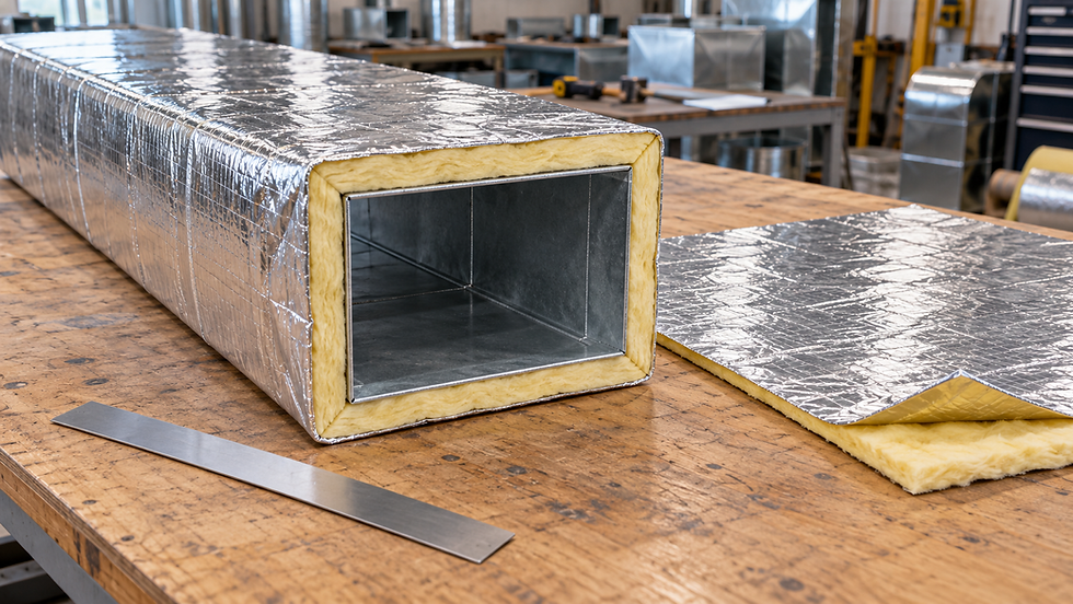
One duct run can have three different quantities
A ductwork schedule may show 48 m² of external metal surface while the insulation installer needs more than 52 m² of faced blanket before fittings or cutting losses. Both quantities can be correct. The error appears when a measurement quantity, a cutting quantity and a purchase quantity share one unlabeled spreadsheet column.
The useful estimating decision is which quantity each rate multiplies. A subcontract measurement rule may use net duct surface; a roll purchase requires a cutting layout. Keep both quantities visible, and establish the specified measurement basis before pricing. This article addresses flexible external duct wrap, rather than internal liner, rigid board fabrication or pre-insulated duct panels.
Start at the external metal boundary
For a straight rectangular duct, external metal perimeter P = 2(W + H), and lateral surface area A = P × L. W and H must represent the outside metal dimensions to be insulated. A schedule may instead state the clear air passage or another nominal convention. Confirm the drawing convention, particularly for internally lined ductwork, before transferring dimensions.
For circular duct, the corresponding metal perimeter is π × external diameter. Neither formula includes end caps, fittings, flanges or separate equipment casings. They also do not include insulation thickness. Give each measured segment a drawing reference, revision, service, size, insulation specification and start/end boundary.
The Owens Corning duct-wrap installation guide similarly starts with the sheet-metal perimeter and then adds a thickness-dependent stretch-out dimension. This is a useful distinction: measuring the substrate establishes the starting geometry, while the selected wrap determines the cut.
Use the selected product’s stretch-out rule
The Johns Manville Microlite FSK data sheet gives a rectangular-duct stretch-out of P + 7 inches for its 1½-inch labeled thickness. That addition already includes a 2-inch facing overlap. The sheet instructs the installer to remove insulation from the overlap area so the facing can lap while the insulation ends butt.
Do not add a second longitudinal lap to a table that already includes one. Equally, do not substitute the perimeter of a hypothetical sharp-cornered outer insulation envelope for a manufacturer’s blanket cut length. Bending, installed compression and seam construction make those different quantities. Rigid-board panel layouts and separate metal jacketing require their own fabrication dimensions.
Johns Manville’s explanation of installed R-value connects excessive wrap compression with reduced thermal performance. A shortage cannot be corrected by pulling every wrap tighter. The specified installed thermal performance and condensation-control design remain constraints on the takeoff.
Worked example: a 24 m rectangular run
Assume a straight, unobstructed rectangular duct with external metal dimensions 600 × 400 mm and net insulated length 24.0 m. For this teaching example only, select the cited 1½-inch wrap row. This is a quantity exercise, not a recommendation that this thickness satisfies the project’s thermal requirements.
Convert dimensions to metres: P = 2(0.600 + 0.400) = 2.000 m. The net lateral metal surface is 2.000 × 24.0 = 48.000 m². Convert the manufacturer’s addition exactly: 7 × 0.0254 = 0.1778 m. Required circumferential cut length is therefore 2.1778 m.
With 24.0 m of net axial blanket coverage, the idealized cut-area subtotal is 2.1778 × 24.0 = 52.2672 m², or 52.27 m² rounded. This is 4.2672 m², or 8.89%, above the metal surface quantity. The difference comes from the specified stretch-out, before any additional offcut allowance.
This subtotal assumes butt-jointed insulation along the run and excludes extra material associated with the actual roll layout. Confirm whether the supplied roll’s stated width describes insulation coverage or includes a facing-only flap. Purchase quantities need the supplier’s usable dimensions, required joints and whole-pack rounding.
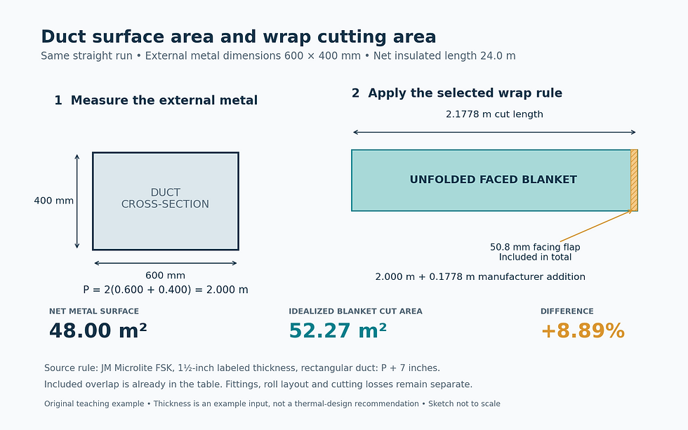
Original quantity example using the cited manufacturer stretch-out. Fittings, roll layout and cutting losses are additional checks.
Give fittings their own boundaries
Break straight lengths at the agreed fitting faces. If a branch assembly already includes its neck, stop the straight branch takeoff at the neck’s end; otherwise that length appears twice. State whether elbows, transitions, offsets, takeoffs, access panels and flange treatments are included in the subcontract surface rate or measured separately.
For a transition, the changing perimeter and sloping faces prevent a single upstream perimeter multiplied by centreline length from being an exact surface calculation. For an elbow, the throat and heel need different cut geometry. Use approved fabrication developments, measured templates or a documented fitting measurement rule rather than hiding every fitting inside a universal percentage.
For example, if hypothetical approved fitting layouts require another 6.40 m² of blanket, the cutting subtotal becomes 52.2672 + 6.40 = 58.6672 m². That 6.40 m² is a stated project input, not a standard allowance. Keep its fitting references so it can be revised when coordination changes.
Turn the takeoff into an order that can be checked
Before ordering, reconcile the straight-run cutting subtotal, separately developed fittings, details at supports and access points, and any separately specified jacket. Then lay out the cuts against available roll sizes. Record reusable remnants, unavoidable offcuts and whole-roll rounding separately so an allowance cannot conceal an omitted fitting.
Ask the estimator and installer to check one representative straight section and one awkward fitting together. Verify the dimension convention, table row, included flap and usable roll coverage. The final schedule should explain how the net measured area becomes a cutting list and how that list becomes an order. That traceable conversion is more useful than an unexplained insulation multiplier.
Sources and further reading
Continue your engineering workflow
The paid 75-page MEP Estimators Handbook PDF covers quantity takeoff, insulation measurement, accessories and tender checks to help structure a complete estimate.



Comments