Duct Leakage Test Acceptance: Reviewing Area, Pressure and Units
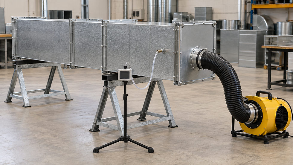
AI-generated editorial illustration; not a verified installation or construction detail.
Start with the test boundary and acceptance rule
A report records 45 cfm leakage at 2.0 in. wg and marks the specimen “pass.” Before accepting that conclusion, check the calculation inputs. The allowable leakage depends on the actual tested surface area, specified leakage class and pressure. A plausible-looking airflow is insufficient.
Identify the duct section on a marked-up drawing, its temporary closures, included fittings and excluded equipment. Then retrieve the project’s specified test method, edition, pressure, direction, leakage criterion and test extent. ASHRAE’s Duct Construction chapter distinguishes procedures for measuring leakage from requirements that set acceptable leakage. The contract and applicable requirements must resolve that distinction.
For causes and repair options, see Nexora’s duct leakage problems and solutions. This review focuses on whether a particular pressure-test result supports acceptance.
Keep three classifications separate
Construction pressure class concerns the pressure duty of the duct assembly. Seal class describes which seams, joints or penetrations must be sealed under the selected specification. Leakage class describes a numerical leakage relationship. Record each separately; the shared word “class” does not make them interchangeable.
Under the I-P leakage-class convention summarized in the TSI PAN341 manual, Appendix B, F = CL × P^0.65. F is cfm per 100 ft² of duct surface, P is the magnitude of test pressure in inches water gauge, and CL is the specified leakage-class number.
Therefore total allowable leakage is Qallow = CL × (A/100) × P^0.65, with A in ft² and Qallow in cfm. Use pressure magnitude in the calculation and record whether the actual test was positive or negative. A fractional power of a signed negative pressure is not the intended calculation.
Audit the surface-area takeoff
Assume a project explicitly requires leakage class 4 at positive 2.0 in. wg for a defined metal-duct specimen. The installed construction and included components are suitable for that test pressure. All dimensions below are for an original teaching example.
The specimen contains a 20 ft long rectangular trunk measuring 3 ft by 2 ft. Its straight-duct surface is 2 × (3 + 2) × 20 = 200 ft². Two branches are each 30 ft long and 1.5 ft by 1 ft: together they contribute 2 × [2 × (1.5 + 1) × 30] = 300 ft².
A checked developed-area takeoff adds 100 ft² for the included fittings, giving A = 200 + 300 + 100 = 600 ft². This is duct surface area, not floor area served or airflow cross-sectional area. In a real takeoff, apply the specified measurement convention to fittings and boundaries; do not automatically treat temporary test blanks as additional permanent duct surface.
The submitted report instead uses 800 ft². The extra 200 ft² belongs to a neighboring section beyond a temporary blank, so it was never pressurized with this specimen. That area cannot enlarge this test’s leakage allowance.
Calculate the allowance and reverse-check the result
At 2.0 in. wg, the pressure factor is 2^0.65 = 1.56917. The correct allowance is Qallow = 4 × (600/100) × 1.56917 = 37.660 cfm.
Assume the valid measured leakage is 45.0 cfm on the required reporting basis. It exceeds the allowance by 7.340 cfm, or 19.49%. The numerical acceptance comparison fails; the team should investigate, correct as necessary and retest under the agreed procedure.
A useful reverse check is CLachieved = Qmeasured/[(A/100) × P^0.65] = 45/[6 × 1.56917] = 4.780. That exceeds the specified class 4.
Using the incorrect 800 ft² would produce an allowance of 50.213 cfm, creating a false pass. A second mistake creates the same problem: replacing the 0.65 exponent with linear pressure scaling gives 4 × 6 × 2 = 48 cfm. Neither calculation describes the specified acceptance relationship.
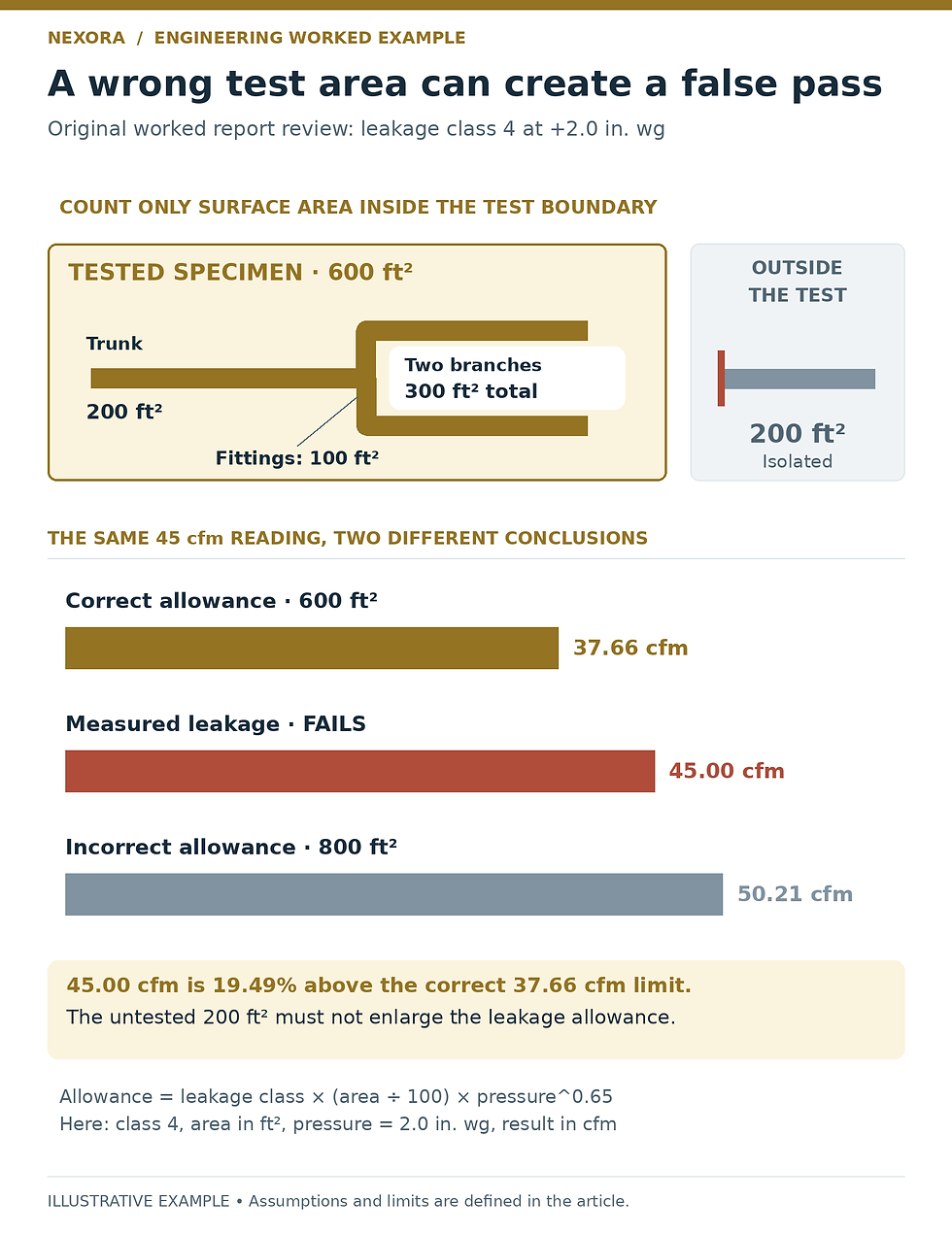
Original Nexora example: the tested 600 ft² specimen allows 37.66 cfm at leakage class 4 and 2 in. wg. Measured 45 cfm fails. Including an untested 200 ft² inflates the allowance to 50.21 cfm and falsely changes the conclusion. The boundary drawing is schematic, not a fabrication layout.
Translate the units without changing the criterion
The original class number belongs to its stated unit convention. For this example, use 1 cfm = 0.47194745 L/s, 1 ft² = 0.09290304 m² and 1 in. wg ≈ 249.08891 Pa. The specimen becomes 55.741824 m², the test pressure 498.17782 Pa, the measured leakage 21.23764 L/s and the allowance 17.77356 L/s.
For a worksheet accepting A in m² and P in Pa while retaining the original I-P CL number, the converted relationship is Qallow(L/s) = 0.001406803 × CL × A × P^0.65. Inserting class 4, 55.741824 m² and 498.17782 Pa returns 17.77356 L/s. The coefficient contains the unit conversion; it is not a new universally defined leakage class.
Do not enter pascals into the inches-water equation or compare a measured m³/s value directly with an L/s allowance. European airtightness letters also use their own defined coefficients and scope. TSI’s PAN341 technical sheet illustrates those relationships. Similar-looking class labels across standards do not establish equivalence.
Check whether the measurement is valid
Confirm calibration status, selected nozzle or flow element, instrument range and pressure-sensing location. Leakage through test hoses, connections and temporary closures can contaminate the result. Use the approved setup-verification procedure and document any permitted correction; an unexplained deduction for “rig leakage” is not auditable.
The TSI low-flow nozzle note explains how low flow can compromise measurement accuracy outside the normal range. A tester capable of pressurizing the duct may still be unsuitable for resolving its small leakage.
Record whether flow is actual or corrected to reference conditions. The PAN341 product information describes automatic standard-condition correction. Check the active instrument setting against the governing test procedure, and avoid correcting the same reading twice.
A pressure-normalized estimate may help diagnose a drifting test, but it does not authorize acceptance at a different pressure. Stabilize at the required pressure, apply the specified duration and retain the raw readings. For a borderline result, resolve measurement uncertainty through the agreed acceptance rule rather than rounding toward a pass.
Issue a report someone else can reconstruct
Attach the test-boundary drawing, section identifiers and surface-area takeoff.
State the governing method, edition, leakage class, pressure direction, test pressure and construction rating.
List equipment serial numbers, calibration evidence, flow range and actual-versus-reference flow basis.
Record stabilized pressure and leakage readings, test duration and relevant ambient conditions.
Show the allowance calculation, unit conversions, achieved class and explicit comparison.
Record defects, repairs, retest references, witnesses and the disposition of excluded sections.
Keep the conclusion bounded: this specimen met or failed this criterion at this pressure. It does not establish that the whole system is leak-free or that leakage equals the same percentage of fan flow in operation. Whole-system airflow verification remains a separate task; Nexora’s fan commissioning guide explains that wider performance check.
Related learning resource
Nexora’s Air Balancing (TAB) Toolkit can organize instrument-calibration records, deficiencies and the wider airflow report. Attach the separately checked leakage-test calculation and boundary drawing so the acceptance evidence stays traceable.
Sources and further reading
Engineering education only. Verify project conditions, applicable requirements and manufacturer data; use qualified professional judgment before design, selection, operation or maintenance decisions.


Comments