HVAC Duct Design Step by Step: Sizing, Pressure Loss and Fan ESP
Last updated: August 2026
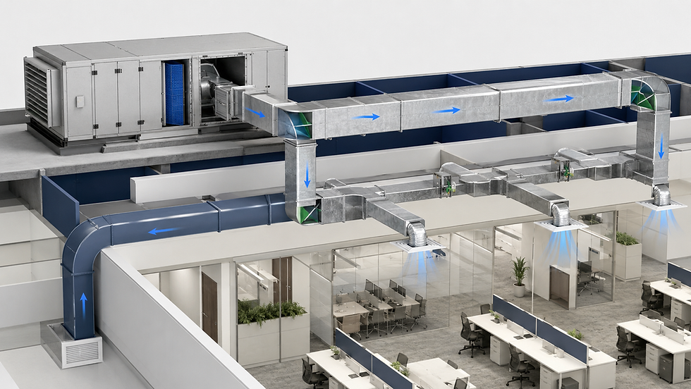
A successful HVAC duct system must do more than connect an air-handling unit to diffusers. It must deliver the correct airflow to every room, control noise, limit pressure loss, maintain the required building-pressure relationships, fit within the available ceiling space and allow the selected fan to operate efficiently.
The complete engineering sequence is:
Cooling load → Room airflow → Air terminals → Duct layout → Section airflow → Duct sizing → Pressure-loss calculation → Critical path → Fan selection → Testing and balancing
Skipping any of these stages can lead to oversized ducts, excessive fan energy, uncomfortable drafts, noisy terminals, insufficient airflow or an HVAC system that cannot be balanced properly. (HVAC Duct Design Step by Step: Sizing, Pressure Loss and Fan ESP)
This guide explains HVAC duct design step by step using practical equations, preliminary design ranges, calculation tables and a complete worked example.
What Is HVAC Duct Design?
HVAC duct design is the process of determining how conditioned, outdoor, return and exhaust air will move through a building.
The designer must establish:
Required airflow for every room and zone
Supply, return, outdoor, exhaust, relief and transfer-air quantities
Diffuser and grille locations
Duct routing
Airflow in each duct section
Appropriate duct dimensions
Air velocity
Straight-duct friction loss
Fitting and component pressure losses
The highest-resistance or critical path
Fan airflow and pressure requirements
Duct pressure class, sealing and leakage requirements
Insulation and vapour-barrier requirements
Acoustic, fire, smoke and access requirements
Testing, adjusting and balancing requirements
Duct design is therefore both an airflow calculation and a system-coordination exercise.
HVAC Duct Design Process at a Glance (HVAC Duct Design Step by Step: Sizing, Pressure Loss and Fan ESP)
A professional duct-design workflow can be summarized in 12 steps:
Establish the design criteria and applicable standards.
Calculate room and zone supply airflow.
Prepare the complete air balance.
Select and locate diffusers, grilles and air terminals.
Develop the supply, return and exhaust duct layout.
Assign duct-section numbers and downstream airflow.
Choose the duct-sizing method.
Calculate duct dimensions, velocity and friction.
Calculate fitting and component pressure losses.
Identify the critical duct path.
determine fan pressure, select the fan and check power.
Coordinate, install, test and balance the system.

The critical path controls the required fan pressure. Pressure losses from parallel branches are not added together.
New to HVAC design? The HVAC Beginner’s Guide is a visual 168-page reference covering HVAC fundamentals, cooling loads, duct sizing, pressure loss, diffusers, grilles and a coordinated small-office design example.
Information Required Before Starting
Before drawing ductwork, collect the following information.
Architectural information
Room dimensions and ceiling heights
Reflected ceiling plans
Wall and ceiling construction
Ceiling void availability
Shafts and risers
Structural beams and slab openings
Door locations
Fire-compartment boundaries
Access-panel requirements
Areas with exposed services
HVAC design information
Room sensible and latent cooling loads
Indoor and supply-air temperatures
Ventilation requirements
Occupancy and operating schedules
HVAC system type
AHU, FCU, VAV or fan locations
Supply, return and exhaust airflow
Space-pressure requirements
Equipment pressure-drop data
Acoustic criteria
Duct material and insulation
Duct pressure and leakage classes
Coordination information
Sprinklers and fire-fighting pipework
Electrical containment
Lighting fixtures
Plumbing and drainage
Structural members
Access zones
Maintenance clearances
Fire and smoke dampers
Ceiling supports
A duct calculation cannot compensate for incomplete or incorrect project information. Record every assumption so it can be reviewed when confirmed information becomes available.
Step 1 — Calculate Room and Zone Airflow
Duct sizing begins with airflow—not with an assumed duct dimension.
For comfort cooling, the room supply airflow is normally calculated from the room sensible cooling load and the temperature difference between room air and the supply air delivered to the room.
Sensible-airflow equation in SI units
V̇ = Qₛ ÷ [ρ × cₚ × (Tᵣ − Tₛ)]
Where:
V̇ = supply airflow in m³/s
Qₛ = room sensible cooling load in kW
ρ = air density in kg/m³
cₚ = specific heat of air in kJ/(kg·K)
Tᵣ = room temperature in °C
Tₛ = supply-air temperature delivered to the room in °C
At standard indoor conditions, approximate values are:
ρ ≈ 1.20 kg/m³
cₚ ≈ 1.006 kJ/(kg·K)
ρ × cₚ ≈ 1.206 kJ/(m³·K)
Therefore:
V̇ ≈ Qₛ ÷ [1.206 × ΔT]
Airflow example
Assume:
Room sensible cooling load = 3.0 kW
Room temperature = 24°C
Supply-air temperature at the room = 14°C
ΔT = 10 K
Then:
V̇ = 3.0 ÷ (1.20 × 1.006 × 10)
V̇ = 0.249 m³/s
Therefore:
Supply airflow ≈ 249 L/s
Sensible-airflow equation in IP units
A common approximate equation at standard air conditions is:
CFM = Qₛ ÷ (1.08 × ΔT)
Where:
Qₛ = sensible load in Btu/h
ΔT = room-to-supply temperature difference in °F
The coefficient varies with air density, altitude, temperature and humidity. Project-specific air properties should be used where the difference is significant.
Important airflow checks
Do not automatically accept the sensible-load airflow as the final value. Compare it against:
Minimum ventilation airflow
Minimum equipment airflow
VAV minimum airflow
Air-change requirements where applicable
Diffuser performance
Required air movement
Humidity-control requirements
Pressurization requirements
Exhaust makeup-air requirements
Heating-mode airflow
Use the room sensible load—not the total load—in the sensible-airflow equation. Total coil duty requires an enthalpy-based psychrometric calculation.
For the complete process from cooling load through airflow, coil duty and equipment selection, see the Cooling Load Design Handbook – Practical HVAC Load Calculations, Airflow, Coil Duty & Equipment Selection.
You can also review Nexora’s practical cooling-load calculation guide.
Step 2 — Prepare the Complete Air Balance
The supply-air quantity is only one part of the system.
Prepare a schedule showing:
Air stream | Purpose |
Supply air | Delivers conditioned air to the space |
Outdoor air | Provides required ventilation and supports pressurization |
Return air | Returns recirculated air to the AHU or return fan |
Exhaust air | Removes contaminants, heat, moisture or odours |
Relief air | Prevents excessive building pressure |
Transfer air | Moves air between rooms without direct supply or return |
Infiltration/exfiltration | Uncontrolled air entering or leaving the building |
For each room, verify the relationship between supply, return, exhaust and transfer air.
A toilet, pantry or dirty utility room may need negative pressure. A clean room, protected lobby or certain healthcare spaces may require positive pressure. General offices are often maintained slightly positive relative to outdoors, subject to the project’s ventilation and pressure-control strategy.
Do not size the supply duct independently while ignoring return and exhaust paths. Air cannot enter a room continuously unless an adequate return, exhaust or transfer route exists.
Step 3 — Select and Position Diffusers, Grilles and
Terminals
Air terminals should be selected before finalizing the duct routing.
A diffuser must be checked for:
Design airflow
Neck size
Pressure loss
Sound level
Throw
Drop
Spread
Terminal velocity
Heating and cooling performance
Ceiling height
Distance from walls and other diffusers
Risk of drafts
Risk of supply-to-return short-circuiting
Do not select a diffuser only because its neck size matches the duct. Use manufacturer-certified performance data at the actual airflow.
Read more about supply-air diffuser throw, drop and spread.
Return-air grilles must be selected using the required airflow, face velocity, free area, neck velocity, pressure loss and acoustic data. Gross grille dimensions are not the same as the effective free area.
See the detailed guide to return-air grille sizing, noise and pressure loss.
Step 4 — Plan the Duct Layout
Prepare a single-line layout before drawing double-line ductwork.
A good layout should:
Use the shortest practical route
Avoid unnecessary elbows and offsets
Reduce abrupt changes in direction
Use gradual transitions
Provide straight lengths before sensitive devices
Allow access to dampers, VAV boxes and sensors
Avoid excessive crossing of other services
Minimize large duct aspect ratios
Provide workable installation and maintenance access
Avoid placing elbows immediately at fan inlets or outlets
Coordinate fire and smoke dampers with fire-rated walls
Keep flexible duct connections short and properly supported
Assign a unique identification number to every duct section. Each section continues until the airflow, size, shape or fitting arrangement changes.
For example:
M1: AHU to first branch
M2: First branch to second branch
B1: Main duct to diffuser group
R1: Return grille to return main
E1: Exhaust grille to exhaust fan
Calculate the airflow in every section by adding all downstream terminal airflows.
Step 5 — Select Duct Shape, Material and Construction
Duct-shape comparison
Duct shape | Advantages | Limitations |
Round | Low perimeter for a given area, efficient airflow, good structural strength and typically lower leakage | May require more ceiling depth |
Rectangular | Easier to fit within shallow ceiling spaces and coordinate around beams | Greater perimeter, potentially higher leakage and pressure loss, reinforcement may be required |
Flat oval | Combines some round-duct efficiency with reduced height | Higher fabrication cost and fewer standard fittings |
Flexible | Useful for short final connections to terminals | High resistance when long, compressed, bent or poorly supported |
Round duct is normally the most aerodynamically efficient. Rectangular duct is often selected because of architectural and coordination constraints.
For rectangular ducts, keep the aspect ratio as close to 1:1 as practical. Some project specifications limit the ratio to approximately 4:1, but this is not a universal code limit. Confirm the applicable specification.
The duct construction must consider:
Operating pressure
Leakage class
Sheet thickness
Reinforcement
Joint type
Sealing
Hangers and supports
Internal or external insulation
Corrosion exposure
Hygiene requirements
Fire-resistance requirements
Use the currently adopted SMACNA technical standards, local mechanical and fire codes, project specifications and authority requirements.
Step 6 — Choose a Duct-Sizing Method
Equal-friction method
The equal-friction method sizes duct sections using approximately the same friction loss per unit length.
Advantages:
Simple and widely understood
Suitable for many small and medium commercial systems
Easy to apply using duct calculators or friction charts
Limitations:
Branches will not automatically have equal resistance
Balancing dampers are still required
Long systems may need larger ducts or more detailed optimization
Static-regain method
The static-regain method reduces duct velocity after branches so that part of the velocity pressure is converted into static pressure.
The approximate relationship is:
Pₛ₂ − Pₛ₁ = Pᵥ₁ − Pᵥ₂ − ΔPₜ,loss
This method can help maintain more uniform static pressure at successive branches, particularly in larger systems.
It requires more detailed calculations and carefully designed transitions.
Velocity-reduction method
The designer selects progressively lower velocities as airflow reduces along the system.
It is straightforward but depends heavily on engineering judgement and may not produce an optimized pressure distribution.
Constant-velocity method
Constant velocity is mainly used where a minimum transport or capture velocity must be maintained, such as certain industrial exhaust and material-conveying systems.
Comfort-air velocity ranges must not be applied to grease exhaust, smoke control, laboratory containment or particulate-conveying systems.
Method comparison
Method | Best suited for | Main consideration |
Equal friction | Small and medium comfort systems | Simple but requires balancing |
Static regain | Large systems with many branches | Better pressure distribution but more calculation |
Velocity reduction | Preliminary and straightforward layouts | Depends on designer-selected velocities |
Constant velocity | Industrial and process exhaust | Must maintain transport or capture velocity |
T-method/optimization | Large or energy-sensitive systems | Balances initial cost and operating energy |
Step 7 — Select Preliminary Velocity and Friction Rate
Velocity affects duct size, pressure loss, noise, capital cost and fan energy.
Higher velocity produces smaller ducts, but it can cause:
Greater friction loss
Higher fitting losses
Increased regenerated noise
More difficult balancing
Higher fan power
Greater leakage potential
Increased vibration
Lower velocity reduces pressure loss and noise but requires larger ducts and more ceiling space.
Preliminary velocity ranges
These values are starting points for commercial comfort systems—not mandatory code limits.
Duct location | Preliminary velocity |
Main supply duct in a shaft or plant area | 5–8 m/s |
Main supply duct above occupied ceilings | 4–6 m/s |
Supply branch | 3–5 m/s |
Final terminal runout | 1.5–3 m/s |
Return main | 3–6 m/s |
Return branch or transfer path | 2–4 m/s |
Noise-sensitive areas such as theatres, studios, hotel rooms and executive offices generally require lower velocities and detailed acoustic analysis.
For equal-friction comfort systems, approximately 0.5–1.0 Pa/m is a reasonable preliminary friction-rate range. Quiet systems usually use the lower end.
Final values must be verified against:
Acoustic criteria
Duct location
System pressure class
Available ceiling space
Fan energy
Project specifications
Applicable energy codes
Manufacturer data
Step 8 — Calculate Round and Rectangular Duct Sizes
The fundamental airflow relationship is:
V̇ = A × v
Therefore:
A = V̇ ÷ v
Where:
V̇ = airflow in m³/s
A = duct cross-sectional area in m²
v = air velocity in m/s
Round-duct diameter
For a circular duct:
A = πD² ÷ 4
Therefore:
D = √[4V̇ ÷ (πv)]
Round-duct example
Required airflow:
V̇ = 0.50 m³/s
Selected velocity:
v = 5 m/s
Area:
A = 0.50 ÷ 5 = 0.10 m²
Diameter:
D = √[(4 × 0.10) ÷ π]
D = 0.357 m
Select the next suitable standard duct size, then recalculate the actual velocity and friction.
Rectangular-duct sizing
For a rectangular duct:
A = a × b
Where:
a = duct width
b = duct height
If the required area is 0.10 m², possible dimensions include:
Width × height | Area | Aspect ratio |
400 × 250 mm | 0.100 m² | 1.6:1 |
500 × 200 mm | 0.100 m² | 2.5:1 |
625 × 160 mm | 0.100 m² | 3.9:1 |
Although all three provide the same gross area, they will not have identical friction, fabrication cost, reinforcement or acoustic performance. The 400 × 250 mm option is normally more efficient than the very flat alternative.
Hydraulic diameter
For direct Darcy–Weisbach calculations in a rectangular duct:
Dₕ = 4A ÷ P
For a rectangular duct:
Dₕ = 2ab ÷ (a + b)
Where P is the wetted perimeter.
Equal-friction equivalent diameter
When using a round-duct friction chart to represent a rectangular duct, an empirical equal-friction equivalent diameter may be used:
Dₑ = 1.30 × (ab)⁰·⁶²⁵ ÷ (a + b)⁰·²⁵
Use consistent dimensions for a, b and Dₑ.
Hydraulic diameter and equal-friction equivalent diameter are different quantities. Do not combine a round-chart equivalent-diameter method with a separate direct hydraulic-diameter calculation.
A preliminary check can also be made using Nexora’s free duct sizing and pressure-loss calculator.
Step 9 — Calculate Straight-Duct Friction Loss
Velocity pressure
Velocity pressure is:
Pᵥ = ρv² ÷ 2
Where:
Pᵥ = velocity pressure in Pa
ρ = air density in kg/m³
v = velocity in m/s
At an air density of 1.20 kg/m³ and velocity of 5 m/s:
Pᵥ = 1.20 × 5² ÷ 2 = 15 Pa
Reynolds number
Re = ρvDₕ ÷ μ
Where:
μ = dynamic viscosity of air
Dₕ = hydraulic diameter
Reynolds number is used to determine the airflow regime and friction factor.
Darcy–Weisbach equation
The straight-duct pressure loss is:
ΔPₒ = fᴅ × (L ÷ Dₕ) × (ρv² ÷ 2)
Where:
ΔPₒ = straight-duct friction loss in Pa
fᴅ = Darcy friction factor
L = duct length in m
Dₕ = hydraulic diameter in m
A practical turbulent-flow approximation is:
fᴅ = 0.25 ÷ [log₁₀(ε ÷ 3.7Dₕ + 5.74 ÷ Re⁰·⁹)]²
Where ε is the duct’s absolute roughness.
Use the roughness value applicable to the actual material and construction. Lined ducts, flexible ducts, poor joints and internal obstructions may have significantly greater resistance than smooth galvanized ductwork.
The friction rate is:
R = ΔPₒ ÷ L
If the calculated loss is 8 Pa over 10 m:
R = 8 ÷ 10 = 0.8 Pa/m
Step 10 — Calculate Fitting and Component Losses
Straight-duct friction is often only a small part of the complete pressure requirement. Elbows, tees, transitions, dampers, terminals, filters and coils can become the dominant losses.
Loss-coefficient method
The fitting pressure loss is:
ΔPfit = K × Pᵥ
or:
ΔPfit = K × ρv² ÷ 2
Where:
K = fitting loss coefficient
Pᵥ = velocity pressure at the specified reference section
The K-factor depends on:
Bend radius
Turning vanes
Aspect ratio
Transition angle
Area ratio
Tee geometry
Branch-to-main airflow ratio
Flow direction
Upstream disturbances
Do not use one generic K-factor for every elbow or tee. Confirm whether the fitting data uses upstream, downstream, branch or common-section velocity.
The ASHRAE Duct Fitting Database provides loss-coefficient data for numerous supply, return and exhaust fittings.
Equivalent-length method
A fitting may also be represented by an equivalent length of straight duct:
ΔPfit = R × Lₑq
Where:
R = straight-duct friction rate
Lₑq = fitting equivalent length
Use either a consistent K-factor method or a consistent equivalent-length method. Avoid double-counting the same fitting.
Component-pressure data
Component | Recommended pressure-loss basis |
Elbows, tees and transitions | Verified K-factor or approved fitting database |
Balancing damper | Manufacturer data at design airflow and damper position |
VAV box | Manufacturer-certified pressure requirement |
Sound attenuator | Manufacturer insertion-loss and pressure-drop data |
Filter | Specified final or dirty pressure drop |
Cooling coil | Wet-coil pressure drop where applicable |
Heating coil | Manufacturer pressure drop at design airflow |
Fire/smoke damper | Certified pressure drop at actual size and velocity |
Diffuser and grille | Manufacturer data at selected airflow |
Louver | Certified pressure drop, including free-area velocity |
Heat-recovery device | Manufacturer-certified pressure drop |
The filter should not be selected only at clean resistance if the fan must operate until the specified final filter condition. Similarly, a wet cooling coil may have a greater pressure loss than a dry coil.
Step 11 — Identify the Critical Duct Path
The critical path—also called the index circuit—is the complete airflow route requiring the greatest fan pressure.
For a recirculating AHU system, the route may include:
AHU or fan outlet
Supply main
Supply branches
Fittings
VAV or control damper
Supply diffuser
Room
Return grille
Return branches and main
Mixing or intake arrangement
Fan inlet
Calculate every complete route separately.
Do not add the pressure losses of parallel branches. The fan airflow is based on the sum of simultaneous terminal airflows, but fan pressure is governed by the complete route with the highest resistance.
The physically longest route may not always be critical. A shorter branch containing a VAV box, sound attenuator, fire damper or high-resistance diffuser may require more pressure.
Step 12 — Calculate Fan External Static Pressure
Static, velocity and total pressure
Total pressure is:
Pₜ = Pₛ + Pᵥ
Where:
Pₜ = total pressure
Pₛ = static pressure
Pᵥ = velocity pressure
Static pressure, total pressure and external static pressure are related but are not interchangeable.
A general external-pressure calculation is:
Required ESP = Supply external losses + Return external losses + Other external losses + Documented system-effect allowance
AHU internal components—such as filters, coils and internal casing accessories—must either:
Be included automatically by the manufacturer’s AHU selection, or
Be added separately to the fan-pressure calculation.
They must not be counted twice.
The exact pressure boundaries required by the manufacturer’s selection software should be confirmed. Some selections request AHU external static pressure, while others require fan static or fan total pressure.
Fan system effect
Poor airflow conditions close to the fan can reduce installed fan performance even when the calculated duct pressure loss appears correct.
Common causes include:
Elbows immediately at the fan inlet
Non-uniform inlet flow
Incorrect inlet transitions
Dampers too close to the fan
Abrupt outlet connections
Insufficient straight duct after the fan
Elbows turning against the fan discharge pattern
AMCA’s system-effect guidance explains why laboratory fan performance may not be achieved when inlet or outlet conditions create swirl and turbulence.
Where practical, improve the layout instead of adding a large pressure allowance to overcome poor fan connections.
Automate the calculation workflow
The HVAC Duct Pressure Loss Design Suite v1.0 organizes circular and rectangular duct sections, velocity, hydraulic diameter, Reynolds number, Darcy–Weisbach friction, fitting K-factor losses, critical-path calculations and recommended fan ESP in one Excel workflow.
It supports SI and Imperial units and produces structured, printable calculation reports—helping reduce repetitive manual calculations while keeping the engineering inputs visible and reviewable.
Step 13 — Select the Fan and Estimate Fan Power
The fan should be selected at the required airflow and pressure duty point.
Check:
Design airflow
Required static or total pressure
Fan efficiency
Motor efficiency
Drive efficiency
Fan speed
Stable operating region
Sound power
Motor power
Available electrical supply
VFD compatibility
Air density
Installation system effect
Future operating scenarios
Fan air power
Pair = V̇ × ΔP
Where:
Pair = air power in W
V̇ = airflow in m³/s
ΔP = fan pressure in Pa
Approximate electrical input
Pelectrical = V̇ × ΔP ÷ (ηfan × ηdrive × ηmotor)
Use fan total pressure with total efficiency, or fan static pressure with static efficiency. Mixing pressure and efficiency definitions produces an incorrect result.
The actual motor must be selected using manufacturer-certified fan performance, motor loading, service conditions and the required operating range.
For deeper coverage, read the duct static-pressure calculation and fan-selection guide.
Step 14 — Check Noise, Leakage, Insulation and Coordination
Acoustic review
Check:
Duct velocity
Terminal sound data
VAV regenerated noise
Damper-generated noise
Fan sound power
Breakout noise
Cross-talk between rooms
Sound-attenuator requirements
Equipment vibration isolation
Duct-borne noise paths
Avoid relying on heavy damper throttling to correct an oversized fan. This wastes energy and can create objectionable noise.
Leakage and sealing
Confirm:
Duct pressure class
Permitted leakage class
Joint and seam sealing
Access-door sealing
Flexible-connection quality
Leakage-test requirements
Testing before concealment or insulation
Leakage increases fan airflow, cooling and heating loads and operating costs.
Insulation and condensation
Check:
Required thermal resistance
Vapour-barrier continuity
External-surface temperature
Condensation risk
Outdoor duct weather protection
Duct heat gain or loss
Acoustic lining requirements
Fire and smoke performance of insulation
Fire and smoke safety
Coordinate:
Fire dampers
Smoke dampers
Combination fire/smoke dampers
Access panels
Fire-alarm interfaces
Fire-rated shafts
Smoke-control modes
Emergency power
Testing and inspection access
Follow the adopted fire code, NFPA requirements where applicable, project specification and local civil-defence or authority requirements.
Controls and balancing
Provide:
Accessible balancing dampers
VAV airflow sensors
Static-pressure sensors in low-turbulence locations
Minimum and maximum VAV settings
Fan speed control
Static-pressure reset where applicable
Outdoor-air measurement
Room-pressure monitoring where required
Complete Worked HVAC Duct Design Example
Consider a small office supplied by one AHU.
Assume:
Room-to-supply temperature difference = 10 K
Standard indoor air density
Total room sensible load = 9.0 kW
Step A — Calculate room airflow
Space | Sensible load | Selected airflow |
Open office | 3.0 kW | 250 L/s |
Meeting room | 2.4 kW | 200 L/s |
Office A | 1.8 kW | 150 L/s |
Office B | 1.8 kW | 150 L/s |
Total | 9.0 kW | 750 L/s |
Step B — Determine section airflow
M1 leaving AHU: 750 L/s
Open-office takeoff: 250 L/s
M2 after first takeoff: 500 L/s
Meeting-room takeoff: 200 L/s
M3 after second takeoff: 300 L/s
Final split: 150 L/s to each office
The route to Office B is initially considered the potential critical path.
Step C — Size the duct sections
Section | Airflow | Duct size | Velocity | Length | Friction rate | Friction loss |
M1 | 750 L/s | 500 × 300 mm | 5.00 m/s | 12 m | 0.74 Pa/m | 8.9 Pa |
M2 | 500 L/s | 400 × 300 mm | 4.17 m/s | 10 m | 0.59 Pa/m | 5.9 Pa |
M3 | 300 L/s | 300 × 250 mm | 4.00 m/s | 6 m | 0.73 Pa/m | 4.4 Pa |
B4 | 150 L/s | 250 × 200 mm | 3.00 m/s | 8 m | 0.55 Pa/m | 4.4 Pa |
Critical-path total | 36 m | 23.6 Pa |
These values are illustrative and assume a direct hydraulic-diameter Darcy calculation with representative galvanized-duct roughness.
Step D — Calculate one fitting loss
At 5 m/s:
Pᵥ = 1.20 × 5² ÷ 2
Pᵥ = 15 Pa
If the exact selected elbow geometry has:
K = 0.25
Then:
ΔPelbow = 0.25 × 15
ΔPelbow = 3.75 Pa
The K-factor is illustrative only. It must not be applied to another elbow without verifying the geometry and reference velocity.
Step E — Prepare the complete pressure budget
Item on critical circuit | Pressure loss |
Supply straight duct | 23.6 Pa |
Supply fittings | 17.4 Pa |
Terminal balancing damper | 10 Pa |
Supply diffuser | 25 Pa |
Return grille, duct and fittings | 55 Pa |
External network subtotal | 131 Pa |
Documented fan installation system effect | 25 Pa |
External selection basis | 156 Pa |
Final-condition filter | 120 Pa |
Wet cooling coil | 85 Pa |
AHU internal casing/accessories | 20 Pa |
Total fan-pressure basis | 381 Pa |
The illustrative fan duty is therefore approximately:
0.75 m³/s at 381 Pa total pressure basis
If the AHU manufacturer’s selection already calculates the internal filter, coil and casing losses, the external-static input would be based on the external network and any verified installation system effect—not the full 381 Pa.
Always confirm the pressure definition and reference points used by the manufacturer.
Step F — Estimate fan input power
Air power:
Pair = 0.75 × 381
Pair = 286 W
If the combined fan, drive and motor efficiency is 55%:
Pelectrical = 286 ÷ 0.55
Pelectrical ≈ 520 W
This is an energy estimate, not a final motor selection. The final motor and fan must be selected from certified manufacturer data.
Special Application: Staircase Pressurization Ductwork
Staircase pressurization is a smoke-control application and must not be designed using ordinary comfort-air duct-sizing assumptions alone.
The design may require evaluation of:
Closed-door leakage airflow
Open-door airflow
Multiple door-opening scenarios
Staircase pressure differential
Door-opening force
Building leakage
Relief-air paths
Fan operating modes
Variable-speed control
Fire-alarm interface
Emergency power
Smoke-control dampers
Level-by-level airflow distribution
Testing and commissioning scenarios
The final criteria must follow the adopted smoke-control standard, fire code, authority requirements and approved fire strategy.
For a structured Excel workflow covering level-by-level leakage, open- and closed-door scenarios, sensitivity checks and print-ready reporting, explore StairPress Pro – Staircase Pressurization Calculator.
Common HVAC Duct Design Mistakes
Sizing ducts from floor area or refrigeration tons without calculating room airflow.
Using total cooling load in the sensible-airflow equation.
Ignoring ventilation, transfer, relief and building-pressure relationships.
Mixing m³/s, m³/h, L/s and CFM.
Selecting diffusers only from neck size.
Using gross grille dimensions instead of manufacturer free-area data.
Confusing hydraulic diameter with equal-friction equivalent diameter.
Using one generic K-factor for every elbow and tee.
Ignoring fitting and component pressure losses.
Adding pressure losses from parallel branches.
Selecting filters using only clean resistance.
Using dry-coil data where wet-coil pressure drop applies.
Double-counting AHU internal component losses.
Adding an arbitrary safety percentage without identifying the uncertainty.
Using long, compressed or sharply bent flexible ducts.
Installing elbows or dampers immediately at fan inlets or outlets.
Using excessive rectangular-duct aspect ratios.
Ignoring leakage, pressure class and sealing requirements.
Failing to coordinate access to fire dampers, VAV boxes and balancing devices.
Selecting a fan by airflow alone.
Trying to correct an oversized fan by heavily throttling dampers.
Omitting testing, adjusting and balancing requirements.
Ignoring altitude and air-density corrections.
Applying comfort-air velocities to specialist exhaust or smoke-control systems.
Final HVAC Duct Design Checklist
Before issuing the design, confirm:
Airflow
Room sensible airflow is calculated.
Minimum ventilation airflow is checked.
Supply, return, outdoor and exhaust quantities balance.
Room-pressure relationships are documented.
Airflow units are consistent.
Terminals
Diffusers are checked for throw, drop, spread, pressure loss and noise.
Return grilles are checked using manufacturer data.
Neck and free-area velocities are acceptable.
Supply-to-return short-circuiting is avoided.
Duct sizing
Every duct section has an identification number.
Downstream airflow is correct.
Velocity and friction are within the design criteria.
Rectangular aspect ratios are reasonable.
Actual velocity is recalculated after selecting standard dimensions.
Pressure loss
Straight-duct friction is included.
Exact fitting losses are included.
Component losses use current manufacturer data.
Final filter and wet-coil conditions are considered.
Supply and return paths are included where applicable.
The critical path is identified correctly.
Parallel branch losses are not added together.
Fan selection
Airflow and pressure definitions are clear.
Internal and external losses are not double-counted.
Fan system effect is minimized or documented.
Fan efficiency, motor power, noise and stable operating range are checked.
VFD and control requirements are coordinated.
Construction and commissioning
Pressure and leakage classes are specified.
Insulation and vapour barriers are coordinated.
Fire and smoke dampers are accessible.
Maintenance clearances are available.
Testing and balancing points are shown.
Leakage testing is completed before concealment where required.
Final airflows and pressure relationships are recorded.
Frequently Asked Questions
How do you design an HVAC duct system step by step?
Calculate room airflow, prepare the complete air balance, select terminals, plan the duct layout, assign section airflows, choose a sizing method, calculate duct dimensions, determine friction and fitting losses, identify the critical path, calculate fan pressure, select the fan and finally test and balance the installed system.
How is duct size calculated from airflow?
Use the relationship V̇ = A × v. Divide the required airflow by the selected design velocity to obtain the duct area. Select a practical round or rectangular size, then recalculate the actual velocity, friction rate and fitting losses using the selected dimensions.
Which duct-sizing method is best?
Equal friction is suitable for many small and medium comfort systems. Static regain can provide better pressure distribution in larger systems. Constant velocity is used for specialist transport or exhaust applications. The best method depends on system size, acoustics, available space, energy targets and operating requirements.
What duct velocity should be used?
There is no single correct velocity for every system. Preliminary commercial comfort ranges may be approximately 4–6 m/s for mains above occupied ceilings, 3–5 m/s for branches and 1.5–3 m/s for final runouts. Final values depend on acoustics, duct location and project requirements.
What friction rate should be used?
Approximately 0.5–1.0 Pa/m is a practical preliminary range for many equal-friction comfort systems. Quiet spaces may require a lower value. The final friction rate should be selected by balancing duct size, fan energy, ceiling space, noise and project specifications.
What is equivalent duct diameter?
Equivalent diameter represents a rectangular duct as a round duct with approximately equivalent friction characteristics. It is mainly used with round-duct friction charts. It is different from hydraulic diameter, which is used in direct fluid-flow calculations.
How is fitting pressure loss calculated?
The common loss-coefficient method is ΔP = K × ρv²/2. The K-factor must correspond to the actual fitting geometry, airflow split and specified reference velocity. Elbows, tees and transitions should not all be assigned the same generic coefficient.
How is the critical duct path identified?
Calculate the complete pressure loss of every route from the fan through the supply system and, where applicable, through the return path. The route with the greatest required pressure is the critical path. It may not be the physically longest route.
What is fan external static pressure?
Fan external static pressure represents the resistance external to the equipment, based on the pressure boundaries defined by the manufacturer. AHU internal filter, coil and casing losses may be calculated separately by the selection software and must not be counted twice.
Is 400 CFM per ton suitable for final duct design?
No. It can be a preliminary rule of thumb for certain comfort systems, but it does not replace room sensible-load, supply-temperature, ventilation, humidity and equipment-performance calculations. Actual airflow per ton varies with sensible heat ratio, coil condition and project design criteria.
Are round ducts more efficient than rectangular ducts?
Round ducts generally have less perimeter for a given area, better structural strength and potentially lower friction and leakage. Rectangular ducts are often necessary in shallow ceiling spaces. Near-square rectangular ducts are normally more efficient than very flat ducts.
How does duct leakage affect fan selection?
Leakage increases the airflow the fan must move to deliver the required terminal airflow. It can also increase heating and cooling energy and disturb room-pressure relationships. Leakage should be controlled through appropriate pressure classification, sealing, construction quality and testing—not only by oversizing the fan.
Conclusion
HVAC duct design is an iterative engineering process. The designer must connect cooling load, ventilation, airflow, terminal selection, duct geometry, pressure loss, fan performance, acoustics and commissioning into one coordinated system.
The most reliable workflow is to:
Establish accurate airflow.
Develop a practical layout.
Size every duct section.
Calculate straight and fitting losses.
Identify the true critical path.
define the correct fan-pressure boundary.
Verify the design through testing and balancing.
For faster, repeatable and traceable calculations, use the Nexora HVAC Duct Pressure Loss Design Suite v1.0.
Calculate duct sections. Check velocities. Analyze fitting losses. Identify the critical path. Determine fan ESP. Prepare a professional report.
Technical References
Engineering Disclaimer
This article provides engineering guidance and preliminary design information. It does not replace project-specific calculations, approved drawings, manufacturer-certified selections, current standards, applicable codes, authority requirements or review by the responsible professional engineer.
Comfort-air design guidance must not be applied directly to smoke control, grease exhaust, hazardous exhaust, healthcare isolation, laboratory containment or material-conveying systems without the applicable specialist design criteria.


Comments