HVAC Duct Design: How to Calculate Friction Loss, Equivalent Length, and Total Static Pressure
Short answer: A reliable HVAC duct friction loss calculation starts by sizing every duct section from its design airflow, calculating straight-duct loss, adding fitting and device losses along each possible route, and identifying the complete critical path. The fan is then selected at the design airflow and the pressure required by that path—not by adding the losses from every parallel branch.
Duct design is a connected engineering process. Air quantity determines duct size; duct size sets velocity; velocity influences friction, fitting loss, noise, and energy; and the final critical-path resistance becomes the pressure duty used for equipment and fan selection.
This guide uses SI units and a worked educational example. For final design, use the project specification, applicable codes, accepted duct and fitting data, selected equipment submittals, and the fan manufacturer’s stated pressure definition.
Want a Repeatable Duct-Pressure Workflow?
The Nexora HVAC Duct Pressure Loss Design Suite is a ready-to-use Excel workflow for organizing duct sizes, segment losses, fitting losses, and fan-pressure checks. It reduces repetitive manual arithmetic and is suitable for MEP engineers, contractors, estimators, and engineering students.
1. Start with Airflow, Duct Size, and Velocity
Begin with the design airflow required at each room or terminal. Add downstream terminal airflows to obtain the flow in each upstream branch and main duct section; do not carry the full system airflow through every downstream segment.
Q = A × VQ = volume airflow rate, m³/s.
A = internal free area of the duct, m².
V = average air velocity, m/s.
For a circular duct, A = πD²/4. For a rectangular duct, A = a × b, using the clear internal dimensions. After selecting a standard duct size, recalculate the actual velocity; the rounded size—not the preliminary target—is what controls the final pressure loss.
Practical Starting Velocities
The following values are practical starting ranges for many comfort-air systems, not universal limits. Acoustic criteria, duct pressure class, shaft space, leakage, energy targets, terminal data, and project standards can require lower or higher values.
Duct section | Starting velocity | Primary check |
|---|---|---|
Main supply | 4–7 m/s | Energy and breakout noise |
Supply branch | 3–5 m/s | Space and regenerated noise |
Terminal runout | 2–3.5 m/s | Room noise and throw |
Return air | 3–5 m/s | Grille noise and fan energy |
General exhaust | 3–6 m/s | Contaminant transport and noise |
A low velocity is not automatically a good design: oversized ducts cost more, occupy more ceiling space, and may create coordination problems. A high velocity is not automatically wrong either, but it usually increases pressure loss, sound risk, and operating energy.
2. Calculate Straight-Duct Friction Loss
Straight-duct friction is the irreversible total-pressure loss caused mainly by wall shear. The Darcy–Weisbach relationship provides the fundamental calculation for a constant-size duct section.
Δpₛ = f × (L / Dₕ) × (ρV² / 2)R = Δpₛ / L = (f / Dₕ) × (ρV² / 2)Δpₛ = straight-duct pressure loss, Pa.
R = friction gradient or friction rate, Pa/m.
f = Darcy friction factor, dimensionless.
L = straight duct length, m.
Dₕ = hydraulic diameter used consistently with the friction method, m.
ρ = air density at the design condition, kg/m³.
V = mean velocity in the section, m/s.
ρV²/2 = velocity pressure, Pa.
The friction factor depends on Reynolds number and relative roughness. Air density, viscosity, duct material, seam condition, internal lining, flexible-duct compression, and construction quality all affect the result; a single friction rate should not be copied blindly across dissimilar duct sections.
Re = ρVDₕ / μRe = Reynolds number, dimensionless.
μ = dynamic viscosity of air, Pa·s.
ε / Dₕ = relative roughness used with an accepted friction-factor correlation.
Rectangular-Duct Caution
The geometric hydraulic diameter of a rectangular duct is Dₕ = 4A/P = 2ab/(a+b). However, the equivalent round diameter used by many HVAC ductulators is a different same-flow, same-friction construct. Do not mix hydraulic diameter, equivalent diameter, and friction-chart assumptions in one calculation.
Using an Equal-Friction Design Rate
Equal-friction sizing is a practical layout method: choose a reasonable design friction rate, size each section for its local airflow, then verify actual velocity, noise, aspect ratio, and available space. Once standard dimensions are selected, recalculate each section’s actual loss rather than assuming the target rate remained exact.
3. Add Fittings with K or Equivalent Length
Elbows, tees, transitions, entries, exits, dampers, and take-offs create local turbulence and separation. Their losses can be calculated by the loss-coefficient method or converted to equivalent straight-duct length; both methods describe the same fitting loss.
Δpᶠ = K × pᵥ = K × (ρVᵣₑf² / 2)Δpᶠ = fitting pressure loss, Pa.
K = fitting loss coefficient, dimensionless.
pᵥ = velocity pressure at the fitting’s specified reference section, Pa.
Vᵣₑf = reference velocity defined by the fitting data source, m/s.
Lₑ = K × Dₕ / fΔpᶠ = R × LₑLₑ = equivalent length of straight duct, m.
Dₕ and f must match the same duct section and friction convention used to calculate R.
Use either K or equivalent length for a fitting—never both. Equivalent length is not a permanent value for “one elbow”; it changes with fitting geometry, duct size, flow condition, and the friction factor used in the conversion.
For project calculations, obtain fitting coefficients from an accepted source such as the ASHRAE Duct Fitting Database. Its data distinguishes round, rectangular, flat-oval, supply, return, and exhaust fittings and calculates loss from the selected geometry and flow.
Pay close attention to the coefficient’s reference velocity. A tee branch coefficient may be referenced to the common section, branch section, or another stated section; using the wrong velocity pressure can materially distort the result.
4. Build the Critical Pressure Path
The critical path is the complete airflow route with the highest required pressure at the design condition. It is often, but not always, the longest route; a shorter branch with small ducts, abrupt fittings, control devices, or a high-resistance terminal can govern.
Draw the network from the air inlet or return terminal, through the air-handling unit or fan, to each candidate supply or exhaust terminal.
Split the layout into constant-airflow duct sections and record the actual flow, size, velocity, length, and material for each section.
For every candidate path, add straight-duct losses, fitting losses, dampers, attenuators, coils, filters, heat-recovery devices, grilles, and terminals that are physically in series.
Compare the complete route totals and identify the highest-resistance path.
Record balancing requirements for lower-resistance parallel branches instead of adding their losses to the fan duty.
Parallel branches do not have their pressure drops added together. At a junction, the pressure difference available across each branch is related to the common upstream and downstream nodes; the fan must satisfy the governing branch while balancing devices absorb excess pressure in easier paths.
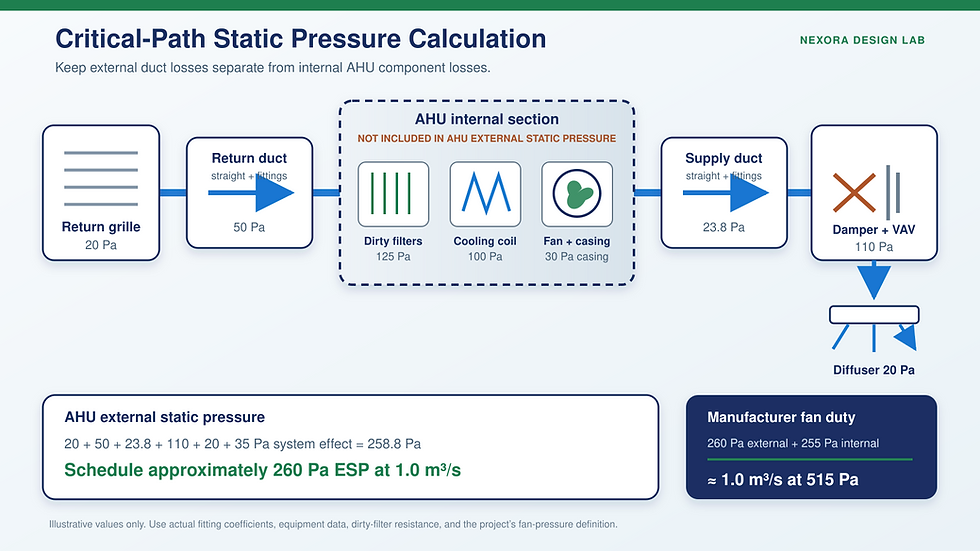
Critical-Path Pressure Map
5. Determine Total External Static Pressure
For an air-handling unit, total external static pressure (TESP or ESP, depending on the schedule terminology) is the resistance of the components and ductwork outside the unit casing at the stated design airflow. The exact equipment boundary must be agreed with the manufacturer and shown clearly on the schedule.
TESPdesign = Δpreturn, external + Δpsupply, external + Δpsystem effectIn field measurements across an air handler, external static pressure is commonly determined from supply static pressure minus return static pressure at specified test locations. Because return static is normally negative, a supply reading of +150 Pa and a return reading of −100 Pa gives 250 Pa across the external system.
TESPmeasured = SPsupply − SPreturn = 150 − (−100) = 250 PaExternal and Internal Losses
Item | Typical boundary | Use in selection |
|---|---|---|
Supply and return ducts | External | Include on governing path |
External fittings and dampers | External | Use K, Lₑ, or selected data |
Grilles and diffusers | External | Use catalog pressure at design flow |
Filters inside AHU | Internal | Use final/dirty resistance |
Cooling or heating coil | Internal | Use selected coil data |
Internal silencer or heat recovery | Check unit boundary | Confirm with AHU supplier |
Fan inlet/outlet system effect | Installation-dependent | Account for or redesign |
For an AHU schedule, give the manufacturer the required external static pressure. The AHU selection software should then add internal filter, coil, heat-recovery, casing, and internal-accessory losses to determine the fan operating pressure. If you independently select a standalone fan, all components in series with that fan must be included.
Fan static pressure and fan total pressure are not interchangeable. Use the same pressure definition, inlet and outlet arrangement, air density, and test basis stated on the certified fan curve; otherwise a numerically correct pressure sum can still produce an incorrect fan selection.
Poor inlet or discharge geometry creates additional system-effect loss that is not represented by simple duct-friction calculations. AMCA’s system-effect guidance explains how elbows, obstructions, swirl, and insufficient straight duct near the fan can reduce installed performance and increase energy, noise, and vibration.
6. Worked Fan Selection Example
Assume a circular supply section carries 1.00 m³/s through a 500 mm internal diameter. The straight length is 22 m. For this educational example, use air density ρ = 1.20 kg/m³, Darcy friction factor f = 0.020, two elbows with K = 0.25 each, and one transition with K = 0.15.
Step 1: Calculate Area and Velocity
A = πD² / 4 = π × 0.50² / 4 = 0.196 m²V = Q / A = 1.00 / 0.196 = 5.09 m/sStep 2: Calculate Velocity Pressure
pᵥ = ρV² / 2 = 1.20 × 5.09² / 2 = 15.5 PaStep 3: Calculate Straight-Duct Loss
R = (f / D) × pᵥ = (0.020 / 0.50) × 15.5 = 0.62 Pa/mΔpₛ = R × L = 0.62 × 22 = 13.7 PaStep 4: Calculate Fitting Loss
Ktotal = 0.25 + 0.25 + 0.15 = 0.65Δpᶠ = Ktotal × pᵥ = 0.65 × 15.5 = 10.1 PaThe same fitting loss can be checked through equivalent length.
Lₑ = Ktotal × D / f = 0.65 × 0.50 / 0.020 = 16.25 mΔpduct + fittings = R × (L + Lₑ) = 0.62 × (22 + 16.25) = 23.8 PaBoth routes agree because the K value, Darcy friction factor, duct diameter, and reference velocity are used consistently. Small differences may appear if rounded intermediate values are used.
Step 5: Add the Complete External Path
Path component | Loss | Basis |
|---|---|---|
Return grille | 20 Pa | Selected data |
Return duct and fittings | 50 Pa | Calculated path |
Supply duct and fittings | 23.8 Pa | Calculation above |
Fire/balancing damper and VAV box | 110 Pa | Selected data |
Supply diffuser | 20 Pa | Selected data |
Documented system effect | 35 Pa | Fan connection layout |
Total external static pressure | 258.8 Pa | Schedule as approximately 260 Pa |
Step 6: Establish the Fan Duty
Assume the AHU manufacturer’s internal losses at this airflow are 125 Pa for the filters at the specified final condition, 100 Pa for the cooling coil, and 30 Pa for internal casing and transition losses. Internal loss is therefore 255 Pa.
Fan selection pressure ≈ 260 Pa external + 255 Pa internal = 515 PaThe preliminary fan duty is therefore approximately 1.00 m³/s at 515 Pa on the manufacturer’s defined static-pressure basis. The AHU schedule should still state 1.00 m³/s at 260 Pa external static pressure if the vendor is responsible for the internal selection.
Step 7: Estimate Input Power
Pinput ≈ Q × Δpfan / ηtotalPinput ≈ 1.00 × 515 / 0.62 = 831 WThis is an energy check, not a final motor selection. The supplier must verify the actual fan curve, fan efficiency, drive and motor efficiency, motor loading, service margin, speed, sound, air density, and stable operating region. A motor around 1.1 kW may be plausible here, but it must come from the selected fan data rather than from rounding the air-power equation alone.
All fitting coefficients and device pressure drops in this example are illustrative. Replace them with the values for the actual geometry, selected product, airflow, filter condition, and project boundary.
7. Verify the Fan Selection
A fan must be selected at an operating point, not merely by matching a nominal airflow or motor power. Review the full fan curve and the proposed installation before accepting the selection.
Confirm the design airflow and required pressure occur within a stable, efficient region of the selected fan curve.
Use the correct fan static or fan total pressure basis and the correct inlet/outlet test configuration.
Correct for actual air density when temperature, altitude, humidity, or gas composition differs materially from rating conditions.
Check fan inlet and discharge geometry, straight-duct length, transitions, elbows, flexible connections, guards, and accessories for system effect.
Verify absorbed power across the expected operating range, not only at the design point.
Check motor rating, drive efficiency, VFD range, electrical characteristics, and site derating requirements.
Review sound power, discharge velocity, vibration isolation, access, casing pressure class, and maintenance clearances.
Evaluate clean and final filter conditions and minimum/maximum VAV operation where applicable.
The U.S. Department of Energy fan-system resources emphasize a systems approach: fan, motor, controls, ducts, fittings, and process components must be evaluated together. Oversizing the fan and then wasting pressure across dampers is not an efficient substitute for accurate design.
8. Common Duct-Design Mistakes
Adding the pressure loss of every supply branch even though branches operate in parallel.
Assuming the geometrically longest branch is automatically the critical path.
Using one airflow, velocity, or friction rate for every duct segment.
Adding both K-method loss and equivalent-length loss for the same fitting.
Using a generic equivalent length for all elbows without checking radius, vane geometry, size, and flow condition.
Applying a fitting coefficient to the wrong reference velocity pressure.
Ignoring the return, outdoor-air, relief-air, or exhaust path that is in series with the fan.
Mixing AHU internal losses into the scheduled external static pressure without telling the vendor.
Using clean-filter resistance where the specification requires a final or dirty-filter condition.
Ignoring fan inlet and outlet system effect because the straight-duct pressure calculation looks small.
Adding an arbitrary percentage safety factor after individual component allowances have already been included.
Selecting a fan by motor kilowatts alone rather than checking the certified airflow-pressure curve.
A transparent pressure-loss schedule prevents most of these errors. Each value should show its source: calculated duct friction, accepted fitting coefficient, selected equipment data, project allowance, or manufacturer selection.
9. Use a Calculation Worksheet or Calculator
A useful worksheet must preserve the route logic, not only produce a final number. Create one row per constant-airflow segment and keep calculated losses separate from catalog device losses.
Worksheet field | Record | Purpose |
|---|---|---|
Segment and path ID | Unique route reference | Prevents branch double-counting |
Airflow | m³/s | Sets area and velocity |
Duct size | mm or m | Defines area and diameter |
Velocity | m/s | Noise and pressure check |
Straight length | m | Friction calculation |
Friction rate | Pa/m | Straight loss |
Fitting data | K or Lₑ | Local loss |
Device loss | Pa | Damper, box, grille, terminal |
Cumulative loss | Pa | Critical-path comparison |
Source or assumption | Reference note | QA and review trail |
For large systems, calculate several candidate routes instead of stopping at the obvious remote terminal. Sort the path totals, retain the top candidates, and update the schedule whenever duct sizes, fittings, air devices, or equipment selections change.
Related Nexora Reading
HVAC Duct Design Step by Step: Sizing, Pressure Loss and Fan ESP: continue the design workflow with this practical Nexora engineering guide.
HVAC Duct Pressure Loss Calculator: Equations, Critical Path & Fan ESP: continue the design workflow with this practical Nexora engineering guide.
10. Limitations and Professional Checks
This method addresses steady design-point pressure loss. Complex networks may need iterative balancing calculations, pressure-independent controls, diversity analysis, smoke-control scenarios, contaminant transport assessment, or CFD where flow distribution and local turbulence cannot be represented adequately by one-dimensional coefficients.
Final designs must also verify local codes, fire and smoke damper requirements, duct construction and leakage class, access, insulation, condensation control, acoustic criteria, testing and balancing tolerances, and the selected equipment manufacturer’s data.
Use current project editions of recognized references. SMACNA’s technical standards cover duct design, construction, inspection, leakage, and testing topics, while ASHRAE and AMCA resources support fitting-loss and fan-system calculations.
Frequently Asked Questions
What friction rate should I use for HVAC duct sizing?
There is no universal value. Many comfort-air designs begin around 0.6–1.0 Pa/m, but the final choice must satisfy velocity, acoustic, energy, space, pressure-class, leakage, and project requirements. Recalculate the actual rate after standard duct sizes are chosen.
Is equivalent length the same for every elbow?
No. Equivalent length depends on the fitting loss coefficient, duct diameter, friction factor, geometry, and reference flow condition. Elbow radius, vane construction, aspect ratio, and nearby disturbances can all change the loss.
Do I add pressure losses from all duct branches?
No. Add components that are in series along each complete path, then compare the path totals. Parallel branches are evaluated separately; the highest required path normally governs and easier branches are balanced.
What is the difference between AHU ESP and fan selection pressure?
AHU external static pressure normally includes losses outside the unit casing. The fan inside the AHU must also overcome internal filters, coils, heat-recovery components, silencers, and casing losses. Give the AHU supplier the external requirement and confirm the selection boundary.
Should filter pressure loss be clean or dirty?
Use the condition required by the specification and operating strategy. Final or dirty-filter resistance is commonly used for fan capability, while clean-filter operation must also be checked so the system does not produce excessive airflow or require wasteful throttling.
Can a fan be selected from airflow and static pressure alone?
Those are the core duty coordinates, but final selection also requires the fan curve, efficiency, absorbed power, motor and drive data, air density, sound, stable operating range, casing class, and actual inlet and discharge arrangement.
Conclusion
Accurate HVAC duct design is a pressure-path problem. Size each segment for its own airflow, calculate straight friction, add fitting losses by one consistent method, include selected device losses, compare complete routes, and carry only the governing external path into the AHU schedule.
Then let the AHU or fan supplier add verified internal losses and select the fan on a certified curve. This disciplined separation makes calculations easier to audit, reduces oversizing, and gives testing and balancing teams a clearer design target.
Turn This Method into a Repeatable Workflow
The Nexora HVAC Duct Pressure Loss Design Suite provides a downloadable engineering workflow for repeated duct and fan-pressure calculations. Use it to reduce setup time, keep assumptions visible, and produce a more consistent calculation record across design, estimation, and review work.
Technical References
ASHRAE Duct Fitting Database and Standard 120 overview: loss coefficients and laboratory testing of HVAC ducts and fittings.
AMCA: system-effect guidance for fan inlet and outlet arrangements.
U.S. Department of Energy: fan-system tools and Improving Fan System Performance resources.
SMACNA technical standards: duct design, construction, leakage, inspection, and testing resources.

Comments