Water-Filled Pipe Support Loads: Include Insulation and Concentrated Valve Weight
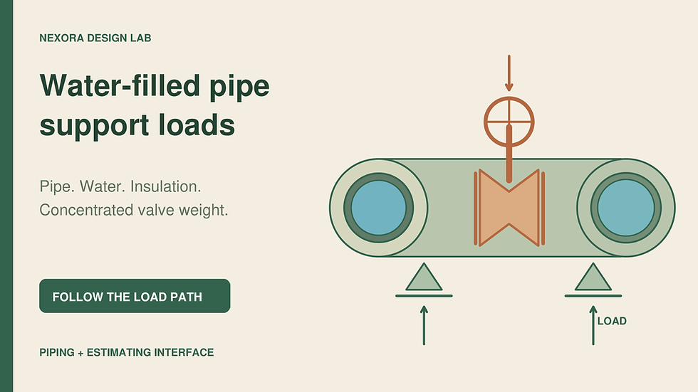
A support takeoff often starts with pipe length divided by an assumed spacing. That can help create an early quantity allowance, but it leaves an important question unanswered: what load reaches each support? Water, insulation and a heavy valve assembly can materially change the answer, particularly when the valve sits close to one end of a span.
Use the following as an estimating-to-engineering interface calculation. It is an original static example, not a support selection, allowable spacing, structural approval or local-code compliance statement. The responsible piping and structural engineers must determine the applicable codes, editions, load combinations, support arrangement and project-specific capacities.
1. Check what a spacing table actually covers
Victaulic publication 26.01, revision D, ©2024, describes suggested spans for specified horizontal steel piping carrying water or similarly dense liquids. Its support-table discussion excludes applications with concentrated loads between supports and critical calculations. It also distinguishes rigid and flexible joint behavior. A table extracted without these qualifications can be applied outside its stated scope.
Before using any spacing reference, identify the pipe material, actual wall thickness, service fluid, temperature, joint system, orientation and table conditions. A spacing appropriate to one pipe system does not establish the capacity of its building attachment. Keep the support location plan and the load schedule as separate, linked documents.
2. Build the operating mass per metre
Assume a straight horizontal steel pipe with outside diameter Do = 0.1143 m and wall thickness t = 0.00602 m. Its assumed inside diameter is Di = Do − 2t = 0.10226 m. Use steel density ρs = 7,850 kg/m³ and water density ρw = 1,000 kg/m³. These are declared illustrative inputs; replace them with project material and fluid data.
Pipe mass per metre is ms = (π/4) × (Do² − Di²) × ρs = 16.08 kg/m. Water mass per metre is mw = (π/4) × Di² × ρw = 8.21 kg/m. Diameter must be in metres in these equations. Using a nominal size in place of actual bore would change the fluid area.
Add dry insulation of assumed thickness ti = 0.050 m and density ρi = 40 kg/m³. The insulation mass is mi = (π/4) × [(Do + 2ti)² − Do²] × ρi = 1.03 kg/m. Assume a further 0.70 kg/m for the specified jacket and minor uniformly distributed accessories. This allowance is invented for the example and must not silently absorb large fittings.
Total distributed mass is approximately 16.08 + 8.21 + 1.03 + 0.70 = 26.02 kg/m, using unrounded intermediate values. With gravitational acceleration g = 9.81 m/s², distributed weight w = 26.02 × 9.81 / 1,000 = 0.2553 kN/m. Keep mass in kg separate from force in N or kN throughout the support schedule.
3. Locate the concentrated load before sharing it
Model one isolated, simply supported span of length L = 4.0 m between supports A and B. Assume a 60 kg valve-and-actuator assembly creates an additional downward point load P = 60 × 9.81 / 1,000 = 0.5886 kN, at distance a = 1.0 m from A. For this simplified example, that mass is additional to the distributed line allowance; replacement pipe length, valve fluid volume and local fittings are already reconciled in the stated model.
Taking moments about A gives RB = wL/2 + Pa/L. Vertical force balance gives RA = wL/2 + P(L − a)/L. Here RA and RB are upward reactions in kN, w is in kN/m, and L and a are in metres. The point load is shared by distance from the supports, rather than automatically split equally.
Distributed-load reaction at each end: wL/2 = 0.2553 × 4 / 2 ≈ 0.5105 kN.
Valve contribution at A: 0.5886 × 3/4 = 0.4415 kN.
Valve contribution at B: 0.5886 × 1/4 = 0.1472 kN.
Total reactions: RA ≈ 0.952 kN; RB ≈ 0.658 kN.
Check equilibrium using unrounded values: RA + RB ≈ 1.610 kN, equal to wL + P. An equal split of the total would give about 0.805 kN per end and understate A’s reaction by about 0.147 kN. Moving the assembly changes that distribution even if the total supported weight stays constant.
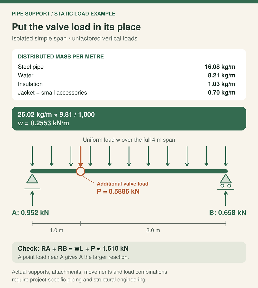
Unfactored static example of an isolated simple span. Loads, dimensions and boundary conditions are illustrative; actual supports and the full load path require qualified project design.
4. Know where the simple model stops
These reactions are unfactored static loads from one isolated span. A real interior hanger may receive load from adjacent spans. Continuous pipe stiffness, flexible joints, support settlement and actual restraint conditions can alter the distribution. A cantilever, branch or vertical riser needs its own model. Additional support close to a valve also changes the system and must be coordinated rather than inserted into the arithmetic without review.
Operating and test states: assess actual fluid densities, fill conditions and applicable test arrangements.
Other actions: evaluate thermal movement, pressure thrust, vibration, transients, seismic and wind effects where relevant.
Load path: assess pipe local stress, clamp or shoe, insulation insert, rod, beam or channel, connections, anchors and supporting structure.
Serviceability: check movement, deflection, drainage requirements, clearances and equipment connection limits.
The Victaulic design data also cautions against placing supports directly on couplings. The exact joint and support manufacturers’ instructions must govern the proposed arrangement. A satisfactory vertical reaction comparison alone does not resolve joint movement, lateral restraint or local attachment details.
5. Turn the engineering response into a complete estimate
Issue a support register with location, served pipe segments, operating weight, concentrated equipment loads, assumed boundary conditions and drawing revision. Request the designer’s support type, material, permissible movements, attachment detail and load basis. Flag unresolved items explicitly so an early quantity allowance is not mistaken for an approved construction detail.
Once reviewed, price the complete assembly: clamp or shoe, load-bearing insulation detail where specified, rods, channels, brackets, connections, anchors, finish and installation access. Count special valve supports and shared trapezes from the coordinated plan. Reconcile which components are included in vendor packages to avoid both omissions and double counting.
For the wider tender workflow, the paid MEP Estimators Handbook is a relevant estimating reference to use alongside the engineer-reviewed support register. The engineering load path and approved support details remain project-specific. A defensible estimate makes those dependencies visible before procurement.



Comments