AHU Outdoor-Air Fraction from Temperatures: Check the Uncertainty Before Trusting the Result

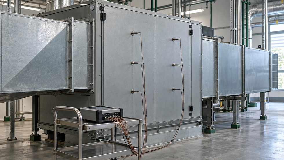
Illustrative engineering scene. The worked calculation below uses explicit example inputs.
Three reasonable temperature readings can produce an outdoor-air fraction that is too uncertain to support a damper adjustment. The difficulty is greatest when outdoor and return temperatures are close: the calculation divides one small temperature difference by another, so modest differential sensor errors become a large fraction of the answer.
Consider two AHU tests that both report 25% outdoor air. In the first, outdoor and return temperatures differ by 6 K. In the second, they differ by only 2 K. With the same stated sensor-error bounds, the possible fractions in the examples below span 18.3–31.7% and 5–45%, respectively. Those results should not receive the same confidence in a commissioning report.
Establish what the temperature ratio represents
Approximate outdoor-air fraction f = (Tmix − Treturn) / (Toutdoor − Treturn). Temperatures may be in °C because only their differences appear. A difference of 1°C has the same magnitude as 1 K.
This relationship assumes steady mixing with negligible added heat and sufficiently similar air-stream heat capacities. It is best treated as an approximate dry-air mass fraction, not automatically as a ratio of actual cubic metres per second at two different temperatures. ASHRAE's moist-air mixing treatment balances dry-air mass, moisture and enthalpy. For a demanding humidity or density comparison, use those balances and convert volumes at their stated conditions.
Locate the mixed-air measurement after adequate mixing but before heating or cooling changes the state. Return air should be measured at the actual mixing-box inlet, including any upstream return-fan heat. Outdoor air should represent the entering stream, rather than a weather sensor warmed by sunlight. A large outdoor-to-return difference improves numerical conditioning; it does not repair a poorly located probe.

Reducing outdoor-to-return temperature separation from 6 K to 2 K widens the illustrative bounded-error interval, even though both central estimates are 25%.
Original example: a 6 K separation
Outdoor air: 30.0°C.
Return air: 24.0°C.
Mixed air: 25.5°C.
Each complete measurement channel is assumed to have a bounded error of ±0.2°C.
The mixing assumptions are accepted for this numerical exercise; additional installation and process errors are excluded.
Nominal f = (25.5 − 24.0) / (30.0 − 24.0) = 1.5 / 6.0 = 0.250, or 25.0%.
The ±0.2°C figure is an illustrative bound on each reported value, not an asserted instrument specification. In a real test, establish the applicable bound from calibration, acquisition, drift and installation evidence. Do not substitute a sensor's display resolution for its accuracy, or assume the sensing element's accuracy covers the entire installed channel.
For this case, the smallest ratio occurs with mixed air low, return air high and outdoor air high. The largest occurs with mixed air high, return air low and outdoor air low. These combinations were checked against all eight corners of the three-input error box. The denominator remains positive throughout that box.
Minimum f = (25.3 − 24.2) / (30.2 − 24.2) = 0.18333. Maximum f = (25.7 − 23.8) / (29.8 − 23.8) = 0.31667. Report the bounded interval as approximately 18.3–31.7%, alongside the nominal 25.0%.
Repeat the same test with only 2 K separation
Keep return air at 24.0°C, but use outdoor air at 26.0°C and mixed air at 24.5°C. The nominal ratio is still 0.5/2.0 = 25%. Keep the same ±0.2°C channel bounds and the same process assumptions. Only the available temperature contrast has changed.
Minimum f = (24.3 − 24.2) / (26.2 − 24.2) = 0.050. Maximum f = (24.7 − 23.8) / (25.8 − 23.8) = 0.450. The admissible interval is now 5–45%.
A hypothetical 20% minimum fraction lies inside both intervals. Neither test, under this deliberately conservative error model, establishes that the true fraction exceeds 20%. That does not establish a ventilation failure either. It establishes that this evidence cannot resolve the decision. The next step is a better measurement, not an arbitrary damper increase.
Choose the test condition from the required resolution
For these interior mixing cases with equal ±e bounds, the worst-case half-width is 2e divided by the outdoor-to-return temperature difference. This follows from the ratio itself, rather than from a prescribed weather threshold. With e = 0.2°C, achieving a half-width no larger than five percentage points needs at least 0.4/0.05 = 8 K of separation, before adding model and installation uncertainty.
PNNL's AHU diagnostic work also recognizes that insufficient temperature separation can make a damper test inconclusive. Its approach supports withholding a fault conclusion when the thermal signal is inadequate. It does not make 8 K a universal acceptance rule: that number belongs only to the bound and resolution chosen in this example.
Do not confuse these bounds with a 95% confidence interval. A statistical uncertainty calculation requires a justified distribution for each input and treatment of correlation. NIST's uncertainty guidance explicitly includes sensitivity coefficients and covariance. The same return-air measurement occurs in both numerator and denominator, so treating those two differences as independent measurements would discard relevant information.
Independent checks that catch spreadsheet errors
Add the same 1°C offset to all three readings. The result must remain unchanged because the common offset cancels.
Change only mixed air by +0.2°C. The nominal fraction changes by 3.33 percentage points for the 6 K case, but 10 points for the 2 K case.
Set mixed air equal to return air or outdoor air. The ideal model should return zero or one, respectively.
If the input bounds allow outdoor and return temperatures to coincide, flag the ratio as ill-conditioned instead of forcing a bounded percentage.
A calculated fraction outside 0–100% is a diagnostic warning. Investigate heat addition, sensor bias, poor mixing, incorrect point mapping or mismatched sample times. Clipping the number to zero or one may make the dashboard look tidy while hiding the evidence needed to find the problem.
Record a defensible field conclusion
Record the three locations, simultaneous readings, AHU operating mode, stability period, uncertainty basis and calculated interval. Where the interval is too wide, repeat during better thermal separation or use an appropriate direct airflow method. If converting the fraction into outdoor airflow, document the total-flow measurement and reference state as well. A fraction alone does not establish an outdoor-air quantity.
For a consistent way to record airflow measurements, instrument calibration status and unresolved deficiencies, get the Air Balancing Toolkit. Its Excel workbook and pocket field handbook support traceable TAB reporting; this temperature-ratio uncertainty calculation still needs a separately documented engineering check.
Continue the calculation review
Sources and calculation basis
Primary references checked on 22 October 2026. The worked examples and diagrams are original illustrative calculations, not manufacturer selections or project approvals. Apply the stated limitations and the requirements governing the actual project.

Comments