AHU Submittal Review: Wet-Coil Pressure Drop and Dirty-Filter Fan Duty
Updated: 7 days ago
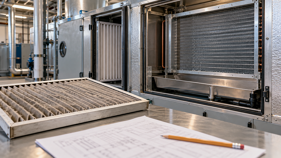
AI-generated editorial illustration; not a verified installation or construction detail.
Begin with the pressure boundary
An AHU supplier lists 450 Pa external static pressure. The consultant’s worksheet lists more than 1,000 Pa fan duty. The difference may be entirely reasonable: one number can describe the connected duct system while the other includes resistance inside the air handler. Approval depends on reconciling those boundaries, not choosing the larger number.
This review addresses a specific submittal problem: a dry-coil, clean-filter selection is being compared with a wet-coil, loaded-filter operating requirement. First identify what each selection includes. Then replace the affected component values and request the corresponding fan selections. Nexora’s broader AHU sizing guide explains the preceding load, airflow and equipment-sizing stages.
Read the footnotes before adding resistance
Create a pressure ledger with component, airflow, pressure loss, operating condition, source page and inclusion status. Separate external ductwork from internal coils, filters, dampers, attenuators and casing effects. Where outdoor and return paths meet, follow the actual network and flows; do not add two parallel inlet paths as though all air passes through both.
Manufacturer tables use different boundaries. For example, fan-performance notes in Trane’s Odyssey catalogue already include a wet coil and the stated standard filter. Adding the complete wet-coil loss again would count that component twice. Another product or selection mode may exclude those items. The footnote for the exact model and configuration controls.
Also distinguish external static pressure, fan static pressure and fan total pressure. Inlet and outlet velocity-pressure terms can prevent a simple one-for-one comparison. Ask the supplier to identify the measurement planes and pressure definition, then reconcile the ledger to that basis. A spreadsheet total labelled “ESP” does not establish what its author included.
Define wet, clean and final conditions precisely
Obtain both dry- and wet-coil air-pressure drops at the scheduled airflow and actual air density. Wet-coil performance must correspond to the selected geometry and cooling condition. Do not assume a universal percentage increase or apply another coil’s wetting correction. Ask whether the quoted loss includes an eliminator, drain-pan restriction or other downstream accessory.
For each filter stage, record model, size, quantity, installed face velocity, initial resistance and the project-approved replacement resistance. If two stages are in series, include both. If a bank consists of parallel filter modules, each module handles only its share of the total flow; their individual pressure drops are not added together.
Camfil’s Hi-Flo XLS data distinguish initial pressure drop at a stated airflow from a final-pressure criterion. That illustrates why “dirty filter allowance” needs an identified basis. Product limits, hygiene requirements and the agreed maintenance strategy can differ. The fictional figures below are not recommended change-out settings.
Original example: one airflow, four operating states
Assume a supply airflow of 5.00 m³/s at a fixed reference density. For this example, the designer and supplier have reconciled every value onto a fan-total-pressure basis, including relevant boundary velocity terms. External-system requirement is 450 Pa; other internal losses are 90 Pa. No further unlisted system-effect or contingency allowance is required by this illustrative ledger.
The selected cooling coil loses 180 Pa dry and 240 Pa wet. The combined filter-bank resistance is 110 Pa clean and 260 Pa at the agreed final condition. These are assumed manufacturer-selection inputs, all at 5.00 m³/s. Keep the airflow constant while comparing the four states.
Dry coil with clean filters: 450 + 90 + 180 + 110 = 830 Pa.
Wet coil with clean filters: 450 + 90 + 240 + 110 = 890 Pa.
Dry coil with final-resistance filters: 450 + 90 + 180 + 260 = 980 Pa.
Wet coil with final-resistance filters: 450 + 90 + 240 + 260 = 1,040 Pa.
Starting from the 830 Pa dry/clean selection, the required correction is (240 − 180) + (260 − 110) = 210 Pa. Therefore 830 + 210 = 1,040 Pa. Adding the full wet-coil and final-filter values instead gives 830 + 240 + 260 = 1,330 Pa, overstating the requirement by 290 Pa.
If the supplier’s selection software asks only for the external requirement and calculates the listed internal components itself, enter the confirmed external input under its own pressure convention. Do not enter 1,040 Pa as external pressure and ask the software to add the same internals again. The 450 Pa used here is already on the example’s reconciled basis; real ESP entry may need boundary conversion.

Original example at constant airflow. Replace the included dry-coil and clean-filter values: 830 + (240 − 180) + (260 − 110) = 1,040 Pa. These assumed values are not universal selection or filter-replacement limits.
Ask for the operating points, not only motor size
Require a fan selection at the wet/final-filter condition and a check at clean resistance. Confirm achievable airflow, speed, absorbed power, operating stability and sound. A larger installed motor does not prove that the fan can reach the required pressure within its speed limit. Conversely, a clean system may need a lower operating speed to avoid excessive airflow.
For an illustrative electrical-power check, assume overall wire-to-air efficiency is 0.65 at the wet/final-filter duty. Input power = 5.00 × 1,040 ÷ (0.65 × 1,000) = 8.00 kW. This efficiency already includes fan, drive and motor losses. Multiplying those efficiencies into the denominator again would introduce another double count.
That result is a screening calculation, not a motor nameplate selection or an annual energy prediction. Efficiency changes with operating point; the supplier must provide its actual values. Fan heat also changes the thermal duty depending on arrangement, covered separately in Nexora’s fan-heat and coil-selection article.
Keep selection resistance and maintenance alarms coordinated
The final filter resistance used to select a fan does not automatically become the BMS alarm setpoint. Establish which pressure taps measure which filter stage, how readings change with airflow, and what manufacturer limit or maintenance criterion the alarm supports. A low-flow reading may remain modest even when resistance has increased substantially.
Record the commissioned clean baseline with simultaneous airflow. Reconcile alarm thresholds, inspection intervals and replacement procedures with the approved maintenance plan. Do not raise a filter alarm threshold merely because the fan has unused speed available. Air cleanliness, filter condition, bypass leakage and equipment limits remain separate considerations.
Close the submittal with a traceable review checklist
Match schedule revision, selected configuration, airflow and density on every page.
Identify pressure definitions, reference planes and every catalogue-included component.
Obtain dry/wet coil losses and initial/final filter losses at the same airflow.
Replace included values with their revised values; add only genuinely missing components.
Review fan curves, speed, motor loading, controls and acoustics at the relevant operating states.
Record approved assumptions, supplier clarifications and the commissioning measurements needed to verify them.
If the fan sheet still cannot be reconciled, return a focused technical query rather than approving a vague spare-pressure allowance. Nexora’s like-for-like quotation review explains how to carry that unresolved technical point into procurement without disguising it as a pricing adjustment. Final acceptance belongs to the project’s responsible reviewer.
Related learning resource
For the external-system side of this review, Nexora’s HVAC Duct Pressure Loss Design Suite organizes duct sections, fitting losses and the critical-path pressure calculation. Attach its output to the supplier’s internal-component ledger and reconcile the pressure boundary before accepting the fan selection.
For the complete unit review, the AHU Selection & Fault Diagnosis Handbook overview shows how coil conditions, fan duty, controls and supplier clarifications fit together. It includes a free ten-page preview and a checked water-flow example. Get the complete handbook.
Sources and further reading
Engineering education only. Verify project conditions, applicable requirements and manufacturer data; use qualified professional judgment before design, selection, operation or maintenance decisions.


Comments