Balancing Damper Pressure Loss: Calculate the Required Branch Resistance
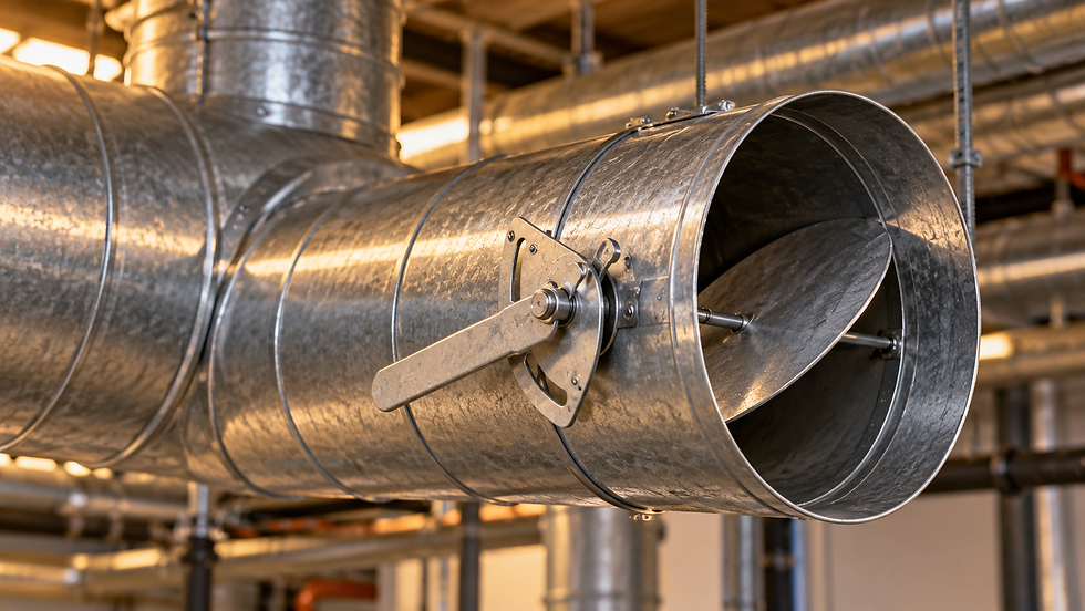
Start with the pressure the branch must absorb
A balancing damper is often entered as a convenient fixed pressure allowance in a duct calculation. During balancing, however, its final loss depends on how much surplus pressure the actual branch must absorb at its target airflow. A fully open product pressure drop and a commissioned throttling loss can be very different numbers.
The useful design question is: at the required branch airflow, what resistance remains after the duct, fittings, terminal and other components are accounted for? Answer it between clearly defined pressure boundaries. This avoids selecting a damper from a nominal loss and discovering on site that it needs a much more restrictive setting.
Build a branch budget with one consistent endpoint
Consider an original example with 185 Pa of available total-pressure difference from the branch takeoff reference section to the selected outlet boundary. Assume the branch must carry 0.600 m³/s. At this airflow, all branch losses except the balancing damper total 95 Pa. These assumed losses include the outlet treatment appropriate to the stated endpoint.
The required damper loss is therefore 185 − 95 = 90 Pa. If the damper’s fully open loss at the same flow is 6 Pa, the fully open branch needs only 101 Pa. Balancing must add another 84 Pa above that fully open condition, giving 90 Pa total across the damper.
Do not add both the 90 Pa required loss and the 6 Pa open-damper loss to the path total. The required 90 Pa already replaces the open condition. Likewise, a pressure allowance already included in an equipment selection must not reappear as a separate branch component.
Convert the required loss into a reference coefficient
ASHRAE’s duct-design method relates fitting loss to velocity pressure at the coefficient’s specified section. For this example only, take a damper coefficient K referenced to the full upstream branch area. With a 400 × 300 mm clear duct, area A = 0.120 m² and velocity V = 0.600/0.120 = 5.00 m/s.
At an assumed density of 1.20 kg/m³, velocity pressure is ρV²/2 = 15.0 Pa. The target coefficient is Krequired = 90/15 = 6.0. The illustrative fully open coefficient is Kopen = 6/15 = 0.40. These are dimensionless coefficients on the same stated reference area.
The coefficient tells you the required aerodynamic resistance, not the blade angle. A handle at 50% travel does not imply half airflow or any universal K value. Blade geometry, number of blades, size, frame and installation all matter. Obtain a pressure-drop curve or coefficient relationship for the actual damper and operating position.
For example, Ruskin’s CD30AF product data uses a model-specific area-factor procedure and identifies its ducted test arrangement and reference air density. Use such manufacturer instructions exactly; do not substitute this article’s assumed K values or assume every published velocity is gross duct velocity.
What happens when the airflow falls?
After the damper is locked, assume its effective K remains approximately constant and the air density is unchanged. At a branch flow of 0.360 m³/s, velocity becomes 3.00 m/s and velocity pressure becomes 5.40 Pa. The damper loss is approximately 6.0 × 5.40 = 32.4 Pa.
The same result follows from 90 × (0.360/0.600)² = 32.4 Pa. The locked damper has not retained a fixed 90 Pa loss; it retains approximately the same resistance characteristic. This distinction matters when estimating part-load pressure distribution or deciding whether a fixed balance setting can satisfy several operating modes.
The square-law estimate applies over a range where the effective coefficient remains suitable. Reynolds-number effects, changing upstream disturbances or a moving damper can invalidate the assumption. In a VAV branch, the terminal control damper also changes resistance, so the fixed balancing damper alone cannot define the branch operating point.
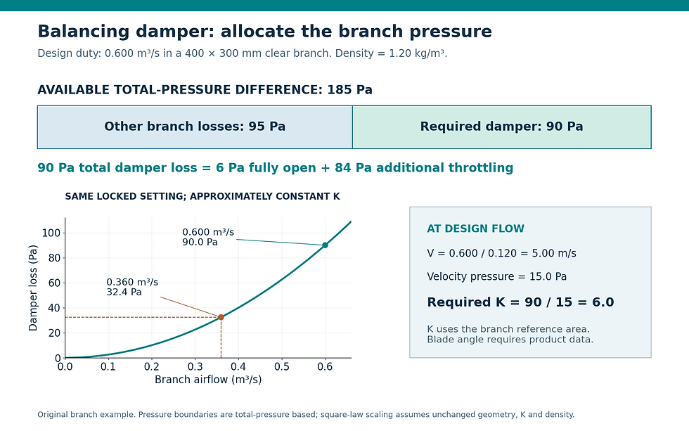
Original branch example. The final 90 Pa damper loss includes the 6 Pa fully open loss; the additional throttling requirement is 84 Pa.
Check the coefficient against the correct branch velocity
Suppose the upstream main carries 1.80 m³/s through 0.240 m². Its velocity is 7.50 m/s and its velocity pressure is 33.75 Pa at the assumed density. Applying the branch-referenced K of 6.0 to that main velocity would predict 202.5 Pa, rather than 90 Pa.
That 2.25-fold error could drive an unnecessary fan-pressure allowance or a mistaken damper selection. Write the reference cross section beside K, and carry branch flow and branch area together through the calculation. This is especially important when a spreadsheet copies a main-duct row to create a branch row.
Select for the actual installation and then prove the balance
Greenheck’s damper guidance points designers to certified performance and model-specific pressure-drop calculations. Review the selected size and installation arrangement, then check allowable velocity, differential pressure, sound generation and access. A damper capable of dissipating the required pressure can still be a poor choice beside a noise-sensitive outlet.
Before throttling, confirm that fan setup, filters, access panels and control modes are ready for the intended balance. Identify the critical path and avoid unnecessarily restricting it. An unexpectedly large required damper loss is a reason to examine branch sizing, network proportions and the fan operating condition, rather than automatically adding resistance everywhere.
Adjust iteratively using measured branch airflow because changes in one branch can alter pressures and flows elsewhere. After the complete system is balanced, recheck affected branches, mark and secure the setting, and record airflow, damper identification, operating mode and the accepted pressure readings.
Pressure taps very close to a blade or abrupt transition can sample disturbed flow. Follow the manufacturer’s measurement arrangement and distinguish a valid pressure-loss test from a convenient nearby static reading. The final report should explain the measurement boundary and any limitations, leaving a repeatable baseline for later alterations.
Sources and further reading
Continue your engineering workflow
Use the paid HVAC Duct Pressure Loss Design Suite Excel workbook to organize duct sections, fitting K-factor losses and critical-path pressure totals in a reviewable calculation schedule.



Comments