Chilled-Water Pipe Bore: Why Nominal Size Can Understate Pressure Loss
Make the pipe schedule part of the hydraulic calculation
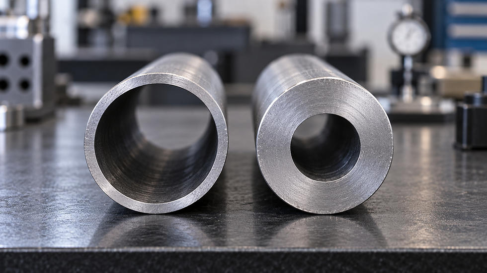
A drawing marked DN100 is not enough information to reproduce a chilled-water pressure-loss result. The calculation needs the internal diameter of the selected pipe product. Two pipes can carry the same nominal size and outside diameter while their wall thicknesses leave different waterways. A seemingly minor substitution can change the critical-path loss without changing any plan annotations.
Treat the material submittal and hydraulic calculation as connected documents. Record the material standard, nominal designation, wall schedule or dimensional series, outside diameter, nominal wall thickness and resulting bore. This is especially important when a higher pressure rating, a different material or a project specification changes the wall after the original sizing exercise.
Separate designation from measured geometry
Wheatland’s A53 pipe dimension sheet lists NPS 4, designated DN100, with a 114.3 mm outside diameter. Its Schedule 40 and Schedule 80 internal diameters are tabulated as approximately 102.3 mm and 97.2 mm. The nominal designation is neither of those bore values. These dimensions are used only for the illustrative comparison below.
For a uniform unlined pipe, nominal bore follows Dinside = Doutside − 2t. However, nominal dimensions are not an inspection certificate for every delivered length. Manufacturing tolerances, internal coatings and deposits can affect the effective waterway. Obtain the current manufacturer’s dimensional data for the specified product and verify whether its published pressure-loss chart already accounts for the actual construction.
Do not transfer a steel-pipe bore table into copper, plastic or multilayer piping calculations because the nominal labels appear similar. In an existing system, confirm the installed material and wall where practicable. Use qualified inspection methods where access, pressure or insulation makes direct identification difficult.
Follow the diameter through the equations
For a fully filled circular pipe, mean velocity is v = 4Q/(πD²). Darcy-Weisbach straight-pipe pressure gradient is Δp/L = f × ρv²/(2D), using the Darcy friction factor. Substituting velocity gives Δp/L = 8fρQ²/(π²D⁵). At fixed flow and approximately unchanged friction factor, bore therefore has a fifth-power influence on straight-pipe loss.
KSB’s head-loss reference explicitly identifies the required diameter as the internal diameter and warns against substituting nominal diameter. Its discussion also distinguishes pipe-wall friction from local component losses. In a detailed calculation, recalculate Reynolds number and relative roughness after a bore change; the friction factor is not generally a fixed property of the pipe material.
Use one friction-factor convention consistently. The following calculation uses Darcy f, not the Fanning factor, which is one quarter of the Darcy value. Record the correlation and units in the worksheet so that a reviewer can reproduce the result rather than just accept a selected pipe size.
Worked example with two DN100 schedules
Assume 8.00 L/s of clean chilled water, density 999.7 kg/m³, kinematic viscosity 1.31 × 10⁻⁶ m²/s, absolute roughness 0.045 mm and 120 m total straight length. These are example inputs representing water near 10°C and an assumed steel surface, not guaranteed properties of every installation. The 120 m is the combined length included in this comparison, not a one-way route that should be doubled again.
For the 102.3 mm bore, v = 0.973 m/s and Re = vD/ν ≈ 76,007. Iterating the Colebrook relation, 1/√f = −2 log10[ε/(3.7D) + 2.51/(Re√f)], gives f = 0.020892. The resulting straight-pipe gradient is 96.70 Pa/m, or 11.60 kPa over 120 m.
For the 97.2 mm bore, velocity rises to 1.078 m/s and Reynolds number to approximately 79,995. Recalculated f = 0.020820 gives 124.45 Pa/m, or 14.93 kPa over the same length. Bore fell about 5.0%, while calculated straight-pipe loss increased 28.7%. The difference is 3.33 kPa in this example, before fitting or equipment effects.
If the spreadsheet blindly used 100.0 mm because the drawing said DN100, it would predict 108.17 Pa/m. That would overpredict the Schedule 40 result by 11.9% but underpredict the Schedule 80 result by 13.1%. The error direction depends on the actual bore; nominal size is not automatically a conservative assumption.
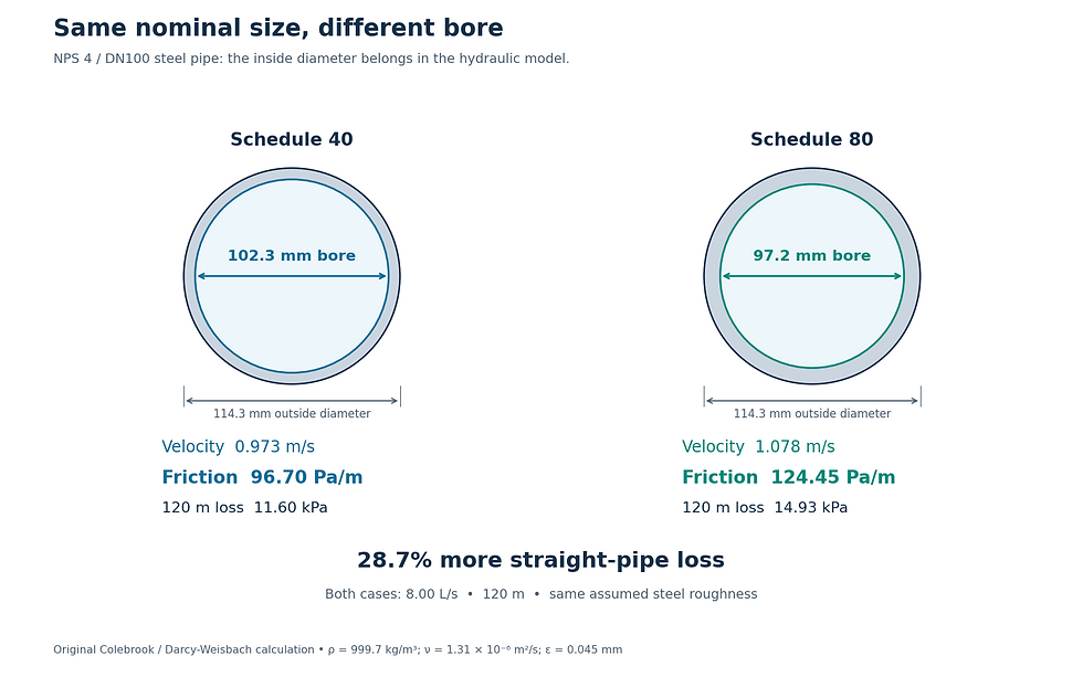
Original calculation using tabulated nominal bores and stated fluid/roughness assumptions. Changing from 102.3 to 97.2 mm increases straight-pipe loss by 28.7%; total circuit loss must be recalculated separately.
Carry the change into the complete circuit
The straight-pipe percentage cannot be applied to total pump head. A coil, strainer, control valve and heat exchanger have their own pressure-loss data. Recalculate each changed fitting with the correct reference velocity or selected-manufacturer curve, and leave unaffected equipment losses on their original justified basis. Avoid counting a fitting both by equivalent length and by a separate loss coefficient.
A pipe substitution may also change joint geometry, reducer locations and available control-valve differential pressure. Re-run the complete candidate critical paths rather than assuming the previous index circuit stays critical. Check pressure rating, supports, expansion, insulation and connection compatibility separately; a hydraulically acceptable bore does not establish mechanical suitability.
Close the review with a traceable schedule
Add an internal-diameter column to the issued calculation and tie each value to a material-submittal revision. Preserve the design flow, fluid temperature, fluid mixture, roughness assumption, correlation and length basis beside it. A reviewer should be able to move from a tagged pipe segment to the selected product data without guessing which generic software library was used.
When installed results differ from the model, check flow measurement, open valve positions, debris and equipment losses before blaming bore. Where dimensions have changed, calculate the incremental effect and update the pump-duty and balancing review. The practical deliverable is an auditable hydraulic model of the pipe that will actually be installed.
Sources and further reading
Continue your engineering workflow
Build a clearer pipe-sizing review with the MEP Pipe Design and Sizing Handbook, a paid reference supplied as PDF and editable Word, including pipe dimension tables, worked examples and calculation templates.



Comments