Cooling-Tower Makeup and Blowdown: A Water Balance That Includes Drift
For a steady-state cooling tower with a conservative dissolved constituent, blowdown equals evaporation divided by cycles of concentration minus one, less the concentrated liquid already leaving as drift and leaks. The useful equation is B = E/(C − 1) − D − L. It works only when its boundary and assumptions are valid. Counting drift as an extra makeup loss without crediting its dissolved-solids removal overstates the blowdown needed for a stated concentration target.
Use this calculation to reconcile water meters, review a treatment proposal or prepare a preliminary water-use estimate. The permitted cycles of concentration remain a water-treatment decision based on the actual water, equipment and operating program.
1. Define the flows and a consistent balance period
Let M be makeup, E evaporation, B intentional blowdown, D drift and L other concentrated liquid loss, all expressed as m³/h on a consistent liquid-water-equivalent basis. Drift means liquid droplets carried away with the air; evaporation means water transferred to the vapor phase. A visible plume is not a direct measurement of either flow.
The EPA mechanical-systems water-efficiency guide identifies evaporation, blowdown, drift, and leaks or overflow as makeup requirements. Include connected basins, equalizer lines and ancillary discharge streams inside a clearly drawn boundary. If a side-stream filter backwashes to drain, account for that discharge too.
Assume average basin inventory is unchanged over the balance period.
Assume recirculating water is sufficiently mixed, so blowdown, drift and the included leaks carry the same constituent concentration.
Assume evaporation carries no material quantity of the selected nonvolatile dissolved constituent.
Assume no material precipitation, deposition, chemical addition or other source/sink changes that constituent inside the boundary.
Use one makeup source or a measured flow-weighted combined makeup concentration, with approximately consistent water density.
These assumptions make an algebraic check possible. Startup, basin filling, rainfall, batch chemical additions or a changing makeup blend can invalidate a short-period steady-state comparison.
2. Derive the two balances before using a shortcut
The water balance is M = E + B + D + L. Let cm be the makeup concentration and ct the recirculating concentration of the selected conservative constituent. Define C = ct/cm, with C greater than 1. The dissolved-solids balance is M × cm = (B + D + L) × ct.
Dividing the solids balance by cm gives M = C(B + D + L). Combining it with the water balance produces B + D + L = E/(C − 1). Therefore B = E/(C − 1) − D − L, and M = E × C/(C − 1). These relations assume enough controllable blowdown remains for B to be nonnegative.
The last equation can look surprising because drift no longer appears explicitly. At fixed evaporation and fixed achieved concentration ratio, additional concentrated liquid loss replaces some intentional blowdown. It does not create a reason to tolerate drift or leakage. Once uncontrolled liquid losses exceed E/(C − 1), the target cannot be maintained by reducing blowdown further.
Terminology matters. The DOE cooling-tower fact sheet presents a simplified balance in which its blowdown term includes other non-evaporative losses. Before comparing two worksheets, check whether “blowdown” means only the controlled drain or the total concentrated liquid leaving the system.
3. Worked example with drift kept explicit
Assume a manufacturer-supported operating-point estimate gives evaporation E = 4.50 m³/h. The treatment specialist has approved C = 5 for this illustrative case. Recirculation is 600 m³/h, the assumed drift fraction is 0.002% of recirculation, and there are no leaks or other liquid discharges. The drift percentage is an example input, not a performance claim for every tower.
Convert the percentage before multiplying: D = 600 × (0.002/100) = 0.012 m³/h. Total concentrated liquid discharge is E/(C − 1) = 4.50/4 = 1.125 m³/h. Controlled blowdown is therefore B = 1.125 − 0.012 = 1.113 m³/h. Makeup is M = 4.50 + 1.113 + 0.012 = 5.625 m³/h.
Check the dissolved-solids balance independently. If the selected constituent is 200 mg/L in makeup and 1,000 mg/L in recirculating water, incoming constituent mass is 5.625 × 0.200 = 1.125 kg/h. Outgoing mass is (1.113 + 0.012) × 1.000 = 1.125 kg/h. Both balances close.
For 24 hours at these unchanged conditions, makeup would be 135.0 m³ and controlled blowdown 26.712 m³. This is an operating-day example, not an annual forecast. Actual operating hours, evaporation, water quality, cell operation and treatment settings can change throughout the year.

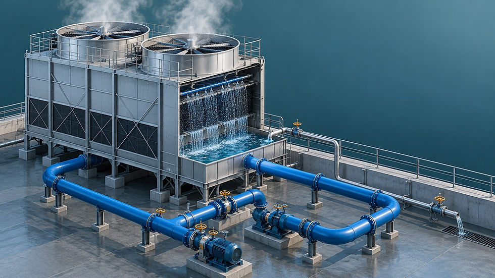
Illustrative steady-state balance at five cycles: drift and controlled blowdown both remove concentrated liquid. Evaporation is a separate input supported by the assumed operating condition.
4. Keep evaporation separate from total heat rejection
Cooling-tower heat rejection includes both sensible and latent transfer. Baltimore Aircoil’s evaporative-cooling explanation describes both mechanisms. A tower’s thermal duty therefore does not, by itself, determine evaporation without additional operating-condition information.
For scale, an assumed 3,500 kW rejection duty divided entirely by an illustrative latent heat of 2,430 kJ/kg gives 1.440 kg/s, or about 5.19 m³/h using 1,000 kg/m³. That calculation assigns the entire duty to evaporation. It must not silently replace the 4.50 m³/h operating-point estimate used above.
Use a tower manufacturer’s evaporation prediction for the relevant conditions, a suitable thermal model, or reconciled operating measurements. State which was used. Likewise, chiller cooling capacity is not automatically its condenser heat-rejection duty: the selected boundary must account for compressor input and other heat streams as applicable.
5. Reconcile conductivity and meters without forcing agreement
Conductivity ratios are useful operating indicators, but conductivity is not a conserved chemical species. Temperature compensation, treatment additions and changing ionic composition can affect the comparison. Confirm the chosen measurement method and acceptable interpretation with the treatment specialist.
In the example, M/B = 5.625/1.113 = 5.054, slightly higher than the true five cycles because the blowdown meter excludes drift. The exact balance ratio under the stated assumptions is M/(B + D + L) = 5.000. An apparent mismatch does not automatically prove a faulty meter or a leak.
If a proposed calculation produces negative blowdown, do not simply replace the answer with zero and keep claiming the requested cycles. With zero blowdown and nonzero uncontrolled loss, the steady-state ratio becomes C = 1 + E/(D + L). Diagnose the inputs, leakage and operating conditions before altering controls.
6. Use a practical commissioning and trend checklist
Confirm makeup and blowdown meter boundaries, units, pulse factors and comparable start/end times.
Record basin level at the beginning and end. Use a longer representative interval if makeup and blowdown operate intermittently.
Obtain the applicable drift information and inspect eliminator condition; do not assume a catalog drift value is a field measurement.
Record makeup and recirculating water samples, treatment changes and all unmetered liquid discharges.
Reconcile both balances and investigate differences larger than the combined measurement and estimate uncertainty.
Have the treatment specialist approve concentration and control changes. This water balance does not replace the site’s water-management or biological-control program.
For treatment background, see HVAC Water Treatment: Preventing Scale, Corrosion and Biological Growth. For thermal operating problems, see Cooling Tower Performance Problems and Solutions.
Continue your engineering workflow
For the wider chilled-water system-design workflow, explore the Nexora Chilled Water System Design Handbook. Get the complete handbook.


Comments