Direct Evaporative Cooling: Wet-Bulb Effectiveness and Added Moisture
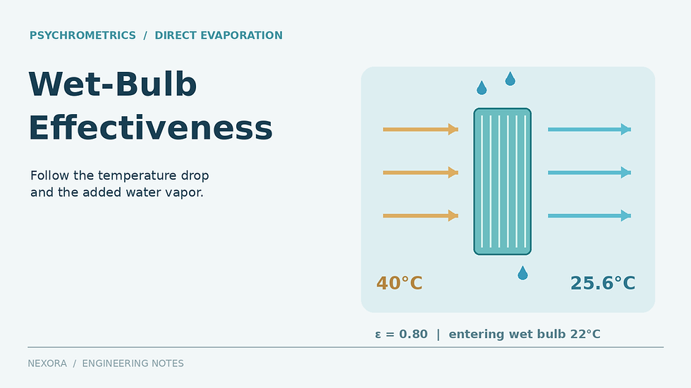
A direct evaporative cooler can produce a large dry-bulb temperature reduction when the entering air is hot and dry. The same device produces much less reduction when the entering wet-bulb temperature rises. To evaluate suitability, calculate both the supply temperature and the moisture added to the air. A temperature-only selection can miss the constraint that matters most to the warehouse, process or downstream cooling system.
1. Define the effectiveness boundary
For a conventional single-stage direct evaporative process, wet-bulb effectiveness is ε = (T_db,in − T_db,out)/(T_db,in − T_wb,in). Temperatures are in °C; differences are kelvins or Celsius degrees. Effectiveness is dimensionless. An 80% value is entered as 0.80, not 80.
Rearranging gives T_db,out = T_db,in − ε(T_db,in − T_wb,in). The EnergyPlus engineering reference describes this direct-stage relationship and explains that effectiveness depends on the media and airflow. Use a value supported at the selected duty, rather than assuming one number applies to every flow setting.
Place the measurement boundary around the wetted stage when using that formula. A downstream fan or sun-heated casing can raise the final delivered temperature. Direct-stage effectiveness also does not describe an indirect or regenerative cooler with a different stream arrangement and rating boundary.
2. Work through a hot, dry entering condition
Assume entering air at 40°C dry bulb, 22°C thermodynamic wet bulb and 101.325 kPa absolute pressure. Actual entering airflow is 5.00 m³/s. Assume ε = 0.80, negligible pressure change, a steady wetted stage and no liquid carryover. These are invented design-review inputs, not a product rating.
The predicted stage leaving dry-bulb temperature is 40 − 0.80(40 − 22) = 25.6°C. At these entering conditions, standard psychrometric calculations give humidity ratio W_in ≈ 0.009152 kg water/kg dry air and specific volume v_in ≈ 0.900172 m³/kg dry air. Dry-air flow is therefore 5.00/0.900172 = 5.5545 kg/s.
The temperature falls by 14.4 K. That is a stage temperature change; the room temperature still depends on sensible loads, supply distribution, exhaust paths and how much air reaches occupied locations. A warehouse with a 30°C design target has only 4.4 K between the calculated supply and target before additional heat gains are considered.
3. Add the water balance to the energy balance
Use h = 1.006T + W(2501 + 1.86T), where h is kJ/kg dry air, T is °C and W is kg/kg dry air. For the illustrative steady adiabatic stage, assume evaporating liquid water enters the air-stream balance at 22°C, with specific enthalpy h_w = 4.186 × 22 = 92.092 kJ/kg water. The selected property relationships follow ASHRAE’s Psychrometrics chapter.
The balance per kilogram of dry air is h_out = h_in + (W_out − W_in)h_w. Combining this with the enthalpy expression gives W_out = [h_in − 1.006T_out − W_in h_w]/[2501 + 1.86T_out − h_w]. This keeps the enthalpy carried by the evaporating water instead of imposing exactly constant moist-air enthalpy.
Entering enthalpy h_in = 63.8108 kJ/kg dry air.
At T_out = 25.6°C, the balance gives W_out = 0.015149 kg/kg dry air, or about 15.15 g/kg.
Moisture increase = 0.005997 kg/kg, approximately 6.00 g/kg dry air.
Evaporation = 5.5545 × 0.005997 × 3600 = 119.92 kg/h, approximately 120 L/h at an assumed water density of 1.00 kg/L.
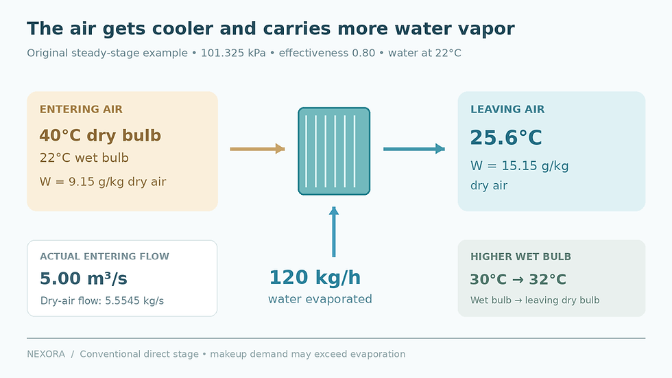
Original steady adiabatic example at 101.325 kPa and 5.00 m³/s entering airflow. Evaporating water is assumed at 22°C; makeup demand may exceed evaporation.
The calculated leaving enthalpy is 64.3631 kJ/kg dry air, slightly higher than entering. Sensible cooling and moisture addition occur together. The process does not remove 81.83 kW of total moist-air enthalpy merely because m_da(1.006 + 1.86W_in)ΔT gives an 81.83 kW sensible-temperature-change quantity.
This idealized water balance excludes external heat transfer, liquid drift, purge, leakage and changing sump inventory. Makeup demand can exceed evaporation. Water-system design needs the manufacturer’s water-quality, concentration-control, cleaning and maintenance requirements as well as the evaporation estimate.
4. Repeat the temperature test for humid weather
Keep entering dry bulb at 40°C and effectiveness at the illustrative 0.80, but increase entering wet bulb to 30°C. The stage now leaves at 40 − 0.80(40 − 30) = 32.0°C. Available temperature reduction has fallen from 14.4 K to 8.0 K without any change in the assumed effectiveness.
If the room target remains 30°C, a 32°C supply cannot offset positive room sensible gains by ordinary sensible cooling alone. That case needs another strategy or a revised operating objective. Repeat the full humidity calculation using the new entering state; the first case’s 120 L/h evaporation must not be copied across.
The UK Energy Technology List’s evaporative-cooler criteria specify entering test conditions and external resistance for reported performance. This is a useful reminder that a published capacity is conditional. Request selection data at the project’s simultaneous dry-bulb and wet-bulb conditions and expected resistance.
5. Check the occupied-space moisture balance
In the first example, the supply contains 15.15 g/kg dry air before it enters the room. Assume a project-specific maximum room humidity ratio of 0.0130 kg/kg. With only this supply, balanced exhaust, no dehumidification and no other dry-air source, the design cannot maintain that lower room value. Occupant or process moisture would make the balance harder.
That conclusion follows from moisture conservation even if the supply temperature looks attractive. Room relative humidity must be calculated at the actual room temperature. It cannot be inferred from the supply’s relative humidity or from a dry-bulb reduction percentage.
A through-flow arrangement needs an engineered exhaust or relief path. Recirculating an enclosed space repeatedly through a direct stage changes its entering condition as moisture accumulates. Coordinate outside-air quality, moisture-sensitive stock, corrosion risk and any downstream dehumidification duty with the responsible engineer.
6. Specify a verifiable operating case
Record simultaneous entering dry bulb, wet bulb or humidity, absolute pressure, stage airflow, outlet state, fan power, pump power and water use. Include fan heat at the correct location. Verify safe water management through the manufacturer and competent project team; this thermodynamic example does not certify hygiene or process suitability.
For the broader sensible and latent load review, see the paid Cooling Load Design Handbook. Keep the manufacturer’s evaporative-stage selection and water-management requirements alongside the load calculation.



Comments