Beyond the Unit: The Revolution of Dynamic Air Flow and Virtual Zoning
Updated: Nov 12

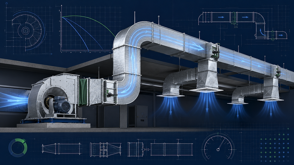
Illustrative AI-generated image. Equipment details are conceptual, not installation instructions.
DYNAMIC AIRFLOW • Room-by-room control works only when sensors, dampers, fans and minimum-flow limits work together.
Choosing an efficient heating or cooling unit is only part of creating comfortable rooms. The distribution system determines where the conditioned air goes, how much reaches each space and what happens when demand changes. A capable unit can still leave a home unevenly conditioned if its air paths do not match the rooms it serves.
Dynamic airflow brings distribution into the control strategy. Rather than treating every room as though it needs the same service at the same time, an engineered system can change delivery as loads and occupancy vary. Virtual zoning adds a software perspective, but the term needs careful interpretation before it becomes a purchasing decision.
A zone displayed in an app is not necessarily a separately controllable thermal zone. Independent comfort requires compatible equipment, physical control authority and a verified airflow path.
What dynamic airflow actually means
Air delivery can change through fan-speed control, modulating dampers, terminal units or a coordinated combination of these devices. The objective is to match service to demand while respecting the equipment and building constraints. Changing a screen setting is only the command; the mechanical system must carry it out.
ASHRAE's Air Handling and Distribution chapter describes controlling the energy supplied to a space by varying airflow, supply temperature or operating time. It also distinguishes a controlled zone from a physical room. Those fundamentals explain why one room can contain several comfort conditions and several rooms can share one control zone.
Residential zoning, commercial variable-air-volume systems and independently controlled room units use different arrangements. A strategy appropriate for a large commercial air handler should not be copied directly onto a small residential system. Equipment limits, ventilation design and available control functions determine what is feasible.
Virtual zoning is a description, not a design standard
The phrase can describe several very different capabilities. Some systems select or average readings from wireless room sensors. Others associate sensors with motorized vents or dampers. More advanced arrangements coordinate those devices with fan output and equipment capacity. The label alone does not tell you which approach is present.
Before accepting a proposal, ask four questions: What is measured in each zone? What physical device changes delivery? How is the central unit coordinated? What happens when only the smallest zone requests conditioning? Clear answers are more useful than a room map filled with coloured temperature bubbles.
A sensor-only arrangement may improve which room influences the thermostat. It cannot make a fixed duct branch independently modulate airflow. Similarly, learning a room's warm-up pattern does not repair an undersized runout or provide a missing return path. Software can reveal physical constraints, but correcting them may require mechanical work.
Start with room demand and a complete air path
Rooms experience different loads because of solar exposure, glazing, envelope construction, occupancy and internal equipment. These loads also change at different times. Sensible zoning groups spaces with compatible needs rather than simply dividing a floor plan into equal areas.
The return path matters as much as the supply branch. A bedroom may perform differently with its door closed, particularly where air must transfer to a central return. Any proposed transfer route needs acoustic, fire, privacy and applicable building-requirement checks. Do not cut openings or modify fire-rated construction based on an airflow sketch alone.
Nexora's HVAC Load and Duct Sizing Professional Calculator is a supporting calculation resource for room loads, airflow and preliminary duct sizing. Use it to organize the design basis before assessing how a control system could vary delivery. It is not a zoning controller and does not certify a proposed installation.
An illustrative airflow calculation
For a simplified sensible-cooling example, assume a room requires 1.2 kW of sensible cooling, the room-to-supply temperature difference is 10 K, air density is 1.2 kg/m³ and specific heat is approximately 1.0 kJ/(kg·K). The sensible relationship is Q = q / (ρ × cₚ × ΔT), giving approximately 0.10 m³/s, or 100 L/s.
If the sensible load falls to 0.6 kW and the same temperature difference remains valid, the arithmetic gives approximately 50 L/s. This illustrates why changing airflow can follow changing demand. It is not a complete room-airflow selection: humidity, outdoor-air requirements, diffuser performance and the equipment's permissible operating range may require a different result.
The temperature difference is also an assumption, not a fixed property of all systems. If supply conditions change, the airflow needed to carry the same sensible load changes too. A control sequence must account for the actual system instead of permanently assigning each room the number from one example.
Static pressure does not disappear when a damper closes
A damper changes the resistance of its branch. That affects the network operating point and can alter both total airflow and the distribution among open branches. The response depends on the fan and its control mode. It is unsafe to assume that all the displaced air simply moves into the room that needs it.
A constant-airflow fan may increase effort to maintain flow within its available range; another fan arrangement may deliver less air as resistance rises. Either response needs checking against selected equipment data. Excessive restriction can also increase noise or expose existing leakage and distribution weaknesses.
Use a complete pressure-path assessment rather than adding every parallel branch together. The Nexora HVAC Duct Pressure Loss Design Suite supports organizing segment losses, fitting losses and fan-pressure checks. Nexora's accompanying duct friction, equivalent length and static-pressure guide explains the calculation workflow and its boundaries.
Minimum airflow is an operating constraint
The smallest active zone is often the hardest zoning case. If that room needs a low airflow but the central equipment requires more, the controller cannot simply ignore the difference. The design must provide a manufacturer-supported way to operate safely and effectively under that condition.
Potential strategies depend on the selected system: capacity modulation, suitable zone grouping, documented minimum damper positions, or a different equipment arrangement may be appropriate. A bypass is not an automatic solution. It changes operating conditions and should only be considered within a supported design, with its energy and temperature implications evaluated.
Do not apply a universal percentage of open vents or a generic minimum L/s figure. Required airflow can vary with cooling stage, heating mode, auxiliary heat and equipment configuration. The permitted range must come from the selected manufacturer's data and commissioning checks.
Closing vents is not a substitute for zoning
The U.S. Department of Energy's home HVAC renovation guide cautions against closing vents and doors as an assumed energy-saving measure. Restricting flow can create pressure imbalances, affect duct connections and interfere with ventilation where the air handler serves that function.
Engineered zoning differs because the dampers, controls, equipment and air paths are assessed together. A motorized register installed without that assessment can reproduce the same restriction as a manually closed vent. Automation does not make an unsuitable airflow arrangement safe.
Low equipment airflow can also contribute to operating problems, including cooling-coil icing or heating-limit operation, depending on the equipment and conditions. Repeated protective shutdowns, unusual noise or deteriorating comfort require investigation rather than more aggressive scheduling. See the manufacturer guidance on restricted airflow and coil icing and furnace high-limit operation.
Diffusers must still work at reduced flow
Lower airflow changes the supply jet. Throw, spread, mixing and occupied-zone air movement can differ from the design-point condition. A room that looks acceptable during a full-output test may feel stagnant, stratified or uneven at part load.
Check terminal data and placement at the expected operating range, not only maximum airflow. Furniture, ceiling obstructions and the relationship between supply and return locations also matter. Nexora's guide to correct HVAC air-terminal placement provides context for assessing the room side of the system.
Temperature control also needs to remain separate from ventilation and moisture management. An unoccupied room or satisfied thermostat does not automatically remove every outdoor-air or humidity requirement. The applicable ventilation strategy must remain effective through the operating modes the zoning controls introduce.
Commission the difficult cases, not just the easy one
Test all zones calling, the smallest zone calling and representative mixed-demand conditions. Include both heating and cooling where applicable.
Measure airflow and external static pressure at the correct test locations, and compare results with the selected equipment's stated limits.
Check room performance with normal door positions, verify sensor readings and record damper commands alongside actual response.
Demonstrate manual override and the documented response to sensor, communications or actuator failure. Keep a clear record of final settings.
For a connected learning path, the Nexora HVAC Duct Design and Sizing Handbook covers airflow, sizing, pressure losses and practical design topics. It supports understanding and review; final selections still require project data, current requirements and professional engineering judgment.
The next step is coordinated performance
The most useful advance is a system that measures room needs, changes delivery within verified limits and remains understandable to its occupants and maintainers. AI may improve prediction or diagnostics, but effective zoning also depends on ordinary control logic, suitable hardware and careful commissioning.
Treat dynamic airflow as an engineering project with a control layer, not an app feature added to an unknown duct network. This article is educational guidance. Any installation or modification needs assessment against local requirements and the selected equipment manufacturer's instructions.
Explore the connected HVAC series
Pair this distribution guide with AI and smart climate control, then check indoor air quality requirements before reducing airflow. For replacement equipment, the heat-pump design guide connects capacity selection with the delivery system.
Comments