Parallel Fan-Powered VAV: Separate Primary and Discharge Airflow
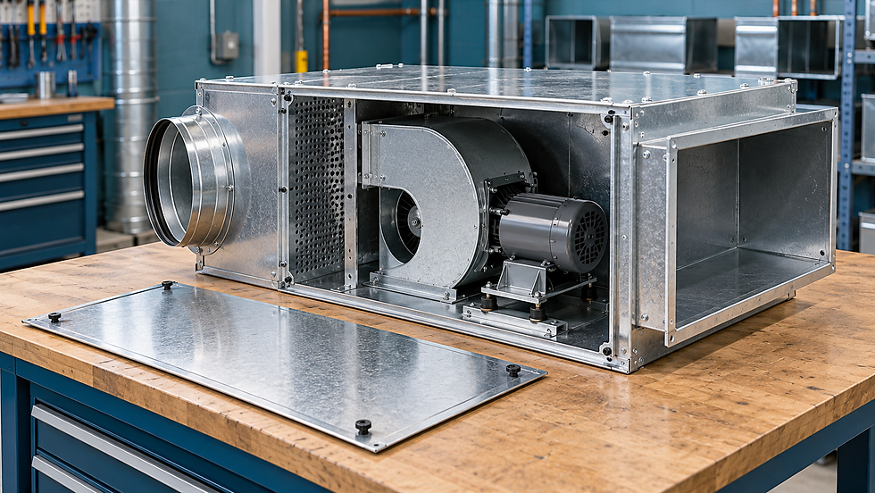
The diffuser and inlet sensor are measuring different flows
A parallel fan-powered VAV terminal can show 120 L/s at its primary-air controller while the room diffusers deliver 400 L/s. That difference may be exactly what the design intended. Before changing a calibration factor, identify whether each reading describes primary air, locally induced air or the combined discharge.
The distinction affects more than the TAB report. It determines the airflow used for coil duty, the resistance seen by the local fan and the temperature delivered to the room. This article follows one heating-mode operating point so those boundaries remain visible through the calculation.
Sketch the two paths before the mixing point
Trane’s parallel fan-powered terminal catalog describes a primary path through the air valve and a separate fan path drawing ceiling-plenum air. The flows combine before entering the downstream distribution. The primary stream does not pass through the parallel fan. Confirm the actual unit arrangement because a series fan-powered terminal has a different fan-flow boundary.
For steady operation without material leakage, mass flow leaving the mixing point equals the sum of the entering mass flows. When volume readings have been corrected to a common density basis, the convenient form is Qdischarge = Qprimary + Qsecondary. If temperatures and densities differ significantly, perform the balance using mass flow or convert readings to a common reference condition.
For this original example, use a common reference density of 1.20 kg/m³, specific heat 1.006 kJ/(kg·K), primary airflow 0.120 m³/s and secondary airflow 0.280 m³/s. The corresponding combined flow is 0.400 m³/s. Ignore fan heat, leakage, moisture effects and casing heat transfer for the screening calculation.
Calculate the mixed temperature and heating duty
Assume primary air enters at 13°C and ceiling-plenum air enters at 25°C. With the stated common-density and sensible-only assumptions, the unheated mixed temperature is (0.120 × 13 + 0.280 × 25)/0.400 = 21.4°C. This is a flow-weighted balance, not the simple average of the two temperatures.
If a downstream coil raises the combined flow to 32°C, its sensible duty is ρQcpΔT = 1.20 × 0.400 × 1.006 × (32 − 21.4) = 5.12 kW. At a room temperature of 22°C, the delivered sensible heating is 1.20 × 0.400 × 1.006 × (32 − 22) = 4.83 kW.
The coil duty exceeds the room heating delivered because the entering mixture is cooler than the room. Keep these two duties separate when reviewing a heating selection. A coil rating and a room heat-loss calculation can legitimately differ, even before allowing for distribution losses or a different design operating point.
Move the coil and the entering-air condition changes
Some units heat only the secondary stream before it mixes with cold primary air. For the same combined 32°C target, the required heated-secondary temperature follows from 0.400 × 32 = 0.120 × 13 + 0.280 × Tsecondary,out. It is 40.14°C.
The secondary-path coil duty is then 1.20 × 0.280 × 1.006 × (40.14 − 25) = 5.12 kW, matching the ideal overall energy balance. The coil now sees 0.280 m³/s entering at 25°C, rather than 0.400 m³/s entering at 21.4°C. Those are different selection conditions despite the equal calculated duty.
A real selection must check available water temperatures and flow, coil pressure losses, fan heat and allowed discharge temperatures. Do not transplant the downstream-coil airflow into a secondary-only coil schedule. Verify the physical coil location from the approved submittal and installed unit before accepting the duty calculation.
The downstream duct sees the sum of both flows
The same manufacturer’s selection guidance distinguishes fan-stream component resistance from downstream resistance carrying combined airflow. Suppose the downstream ducts and outlets require 100 Pa at a 0.600 m³/s cooling reference condition. With unchanged distribution settings, a square-law estimate at 0.400 m³/s gives 100 × (0.400/0.600)² = 44.4 Pa.
Using the local fan flow of 0.280 m³/s in that downstream calculation would give only 21.8 Pa. It would understate this part of the fan’s pressure requirement by 22.7 Pa. The primary stream also enters the downstream duct, so the local fan must discharge against the pressure created by the combined flow.
If a secondary-path coil has an assumed 35 Pa loss at 0.280 m³/s, the illustrated component budget is 35 + 44.4 = 79.4 Pa, before other applicable losses. Match this budget to the manufacturer’s fan-curve boundary. Do not add internal components twice if the supplied curve or selection already includes them.
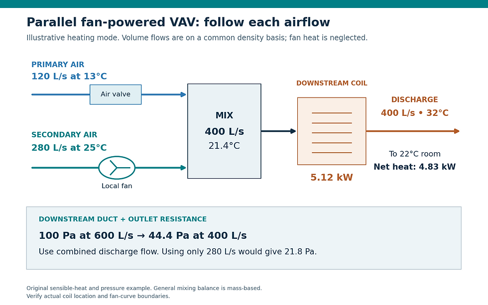
Original heating-mode example on a common airflow-density basis. Primary, secondary and combined discharge flows belong to different measurement and selection boundaries.
Commission each flow on its own boundary
Price’s fan-powered terminal installation manual separately checks primary flow and notes that heating-mode outlet flow combines primary and fan airflow. Label the design primary minimum, design secondary heating flow and design combined discharge flow as separate report fields. Verify primary airflow with a method appropriate to the inlet pickup and low-flow range. Measure all connected outlets to establish discharge flow during the same stable heating condition.
Where a direct secondary-flow measurement is impractical, discharge minus primary gives an inferred secondary flow. Preserve the uncertainty of that subtraction. For illustrative independent standard uncertainties of 0.020 m³/s on discharge and 0.006 m³/s on primary, the inferred secondary uncertainty is √(0.020² + 0.006²) = 0.0209 m³/s, about 7.5% of 0.280 m³/s.
Check local fan operation, backdraft-damper movement, accessible plenum inlet conditions and coil configuration. Measure temperatures with enough spatial coverage to detect incomplete mixing. A single sensor immediately after the junction may see one stream preferentially; use a representative downstream location when checking the mixed-air balance.
Never recalibrate the primary sensor to make its 120 L/s reading match a 400 L/s diffuser total in this heating example. That would impose a 3.33 multiplier on quantities with different boundaries. Restore overrides and record the final mode, primary flow, fan command, combined flow and temperatures. These paired readings make future fault diagnosis much clearer.
Sources and further reading
Continue your engineering workflow
The paid Air Balancing (TAB) Toolkit provides an Excel workbook for branch and terminal airflow results, instrument records and deficiencies, plus a pocket PDF handbook for a consistent field-reporting workflow.



Comments