Pipe Hanger Takeoff: Separate Support Stations from Rod and Anchor Quantities

Original illustrative engineering schematic. The worked calculation below uses explicit example inputs.
A pipe takeoff can contain the correct metres and still produce the wrong hanger order. Dividing total pipe length by a spacing mixes several different quantities: unsupported intervals, support locations, pipe-contact components and attachments to the building. Shared trapezes make the difference especially important. Two parallel pipes may use one frame at a station, but still need two separate pipe-contact assemblies.
The worked example below is a quantity reconciliation from an assumed approved support layout. It does not establish allowable spans, select anchors or prove structural adequacy. The piping and structural designers must resolve loads, movement, insulation, corrosion protection, attachment conditions and applicable project requirements before the estimator treats the arrangement as construction information.
1. Define the four counting units
Support station: a unique physical location identified on the coordinated route, not simply a mark repeated on two pipe drawings.
Support assembly: the approved frame or individual hanger at that location. One station can contain more than one assembly if the detail requires it.
Pipe contact: one scheduled clamp, shoe, saddle or insulated support assembly contacting one pipe. The example uses one contact assembly per supported pipe at each location.
Structural attachment: the approved connection between a rod or bracket and the building. Its component quantity comes from the attachment detail, not directly from the pipe count.
Eaton’s support guidance explains that structural obstructions, member loading and the available building connections can change the required support arrangement. Accordingly, a length-based estimate is only a starting check. Record the reviewed drawing and detail revisions behind the final locations, rather than presenting a generic spacing assumption as a manufacturer-approved design.
2. Count bays before endpoint supports
For an isolated straight segment with a support at both ends, no additional local requirements and a stated maximum interval s, the smallest geometric number of bays is ceiling(L/s). The corresponding number of stations is that bay count plus one. Ceiling means rounding upward to the next whole number. This formula is a check on a simplified layout, not permission to relocate supports or load an equipment nozzle.
Illustrative isolated line B: L = 10.0 m; approved maximum interval for this example s = 3.0 m.
Minimum geometric bays = ceiling(10.0 ÷ 3.0) = 4.
Stations with both endpoints supported = 4 + 1 = 5.
Assumed approved positions = 0, 2.5, 5.0, 7.5 and 10.0 m.
Using 10/3 and rounding to four hangers misses one endpoint in this particular boundary. Conversely, adding an endpoint allowance to every drawing segment can duplicate a real shared support. A bend, tee, equipment connection or expansion arrangement may impose additional requirements. Where the route is not an isolated segment, count the actual location IDs and use the formula only to detect possible omissions.

Schematic of seven shared stations plus one local valve support in the example corridor. Together with twelve individual hangers described in the article, the complete takeoff is 20 assemblies, 27 pipe contacts and 28 rods/attachments, with 31.8 m rod and 9.6 m crossbar cut length. This quantity example does not specify safe spacing, loads or structural selection.
3. Reconcile shared and independent locations
Corridor A contains two parallel 18 m pipes. The assumed approved drawing shows seven shared two-rod trapezes at stations 0, 3, 6, 9, 12, 15 and 18 m. These are seven frames carrying fourteen pipe contacts, not fourteen frames. A separately engineered local valve frame at station 7.5 m supports only the supply pipe. It has its own frame ID and one pipe contact.
The same package also contains line B with its five single-rod hangers, plus two physically independent branches. Branch C is 4.8 m long with three single-rod hangers at 0, 2.4 and 4.8 m. Branch D is 7.2 m long with four at 0, 2.4, 4.8 and 7.2 m. No branch endpoint shares a frame with another listed segment; that is an explicit assumption established by the example drawing.
Corridor A: 7 regular trapezes + 1 local valve frame = 8 assemblies.
Other assemblies: 5 + 3 + 4 = 12 individual hangers.
Total support assemblies = 8 + 12 = 20.
Pipe contacts = (7 × 2) + 1 + 5 + 3 + 4 = 27.
Rods = (8 × 2) + 5 + 3 + 4 = 28.
The 20, 27 and 28 totals are all correct because they describe different things. Keep those units visible in the takeoff. Eaton’s sample hanger specification also distinguishes shared trapeze arrangements and intermediate support requirements. It is a useful scope prompt, but its provisions do not replace the specification and engineered details adopted for the actual project.
4. Expand the approved assemblies into cut lengths
Assume all eight corridor frames use two rods, each with a final scheduled cut length of 1.40 m, and one crossbar with a final cut length of 1.20 m. The five line-B hangers each use one 0.90 m rod. The seven branch hangers each use one 0.70 m rod. These are fabrication cut lengths already including the required engagement and detailing allowances, not just clear ceiling-to-pipe dimensions.
Corridor rod cut length = 8 × 2 × 1.40 = 22.40 m.
Line-B rod cut length = 5 × 0.90 = 4.50 m.
Branch rod cut length = 7 × 0.70 = 4.90 m.
Total rod cut length = 22.40 + 4.50 + 4.90 = 31.80 m.
Crossbar cut length = 8 × 1.20 = 9.60 m.
Assume the approved connection schedule calls for one structural attachment assembly per rod, so this package needs 28 attachment assemblies. This is not a general rule that every support uses one anchor or that all anchor types are interchangeable. An attachment kit can contain several fasteners or a proprietary insert. Expand it only after confirming the exact supply description and avoid counting a kit and its included pieces twice.
5. Keep engineering, installed quantities and purchasing separate
A total of 31.80 m of cut rod does not specify how many stock lengths to buy. Purchasing must retain diameter, grade, finish and cut-piece lengths, then allow for feasible cutting patterns, kerf, approved couplings where applicable and usable remnants. Do not combine different rod specifications into one order simply because their lengths add neatly. The 9.60 m crossbar total needs the same treatment.
Likewise, a count of 27 pipe contacts does not identify their sizes or insulation details. Group them by approved clamp or shoe type, pipe outside diameter, load-bearing insulation arrangement, finish and location. Thermal movement requirements can distinguish otherwise similar-looking assemblies. Seismic bracing, guides, anchors for pipe movement and vibration-isolated supports remain separate scope unless expressly included in a scheduled assembly.
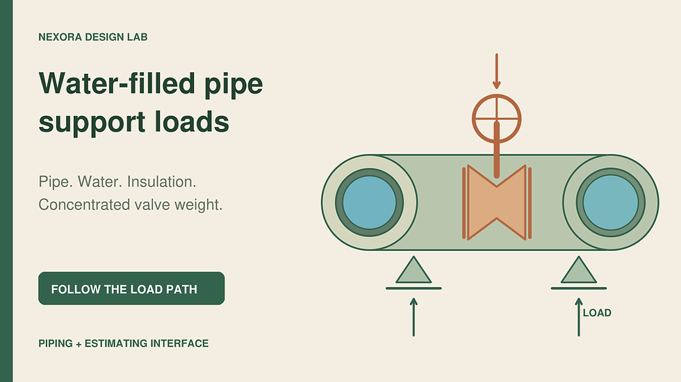
Keep the load calculation linked but distinct. Nexora’s pipe-support load example shows why fluid, insulation and concentrated valve weight matter; this article instead counts the components after the support arrangement has been reviewed.
6. Issue a register that can survive a revision
Assign one ID to each physical support assembly and list every pipe segment it serves. Cross-reference repeated appearances instead of creating another assembly.
Reconcile all twenty assembly IDs against twenty drawing locations and twenty approved detail references or type assignments.
Check the component totals independently: eight two-rod frames give sixteen rods; twelve single hangers give twelve more.
Separate supply-included parts, items to procure, cut lengths and stock-order quantities. Preserve all of them rather than overwriting one with another.
After a revised route, compare changed location IDs, rod drops and supported pipes. An unchanged pipe length does not prove the support quantities are unchanged.
The resulting BOQ is more useful than a percentage allowance for supports: it explains which assemblies exist, which pipes they support and how their components were derived. The MEP Estimators Handbook provides a broader reference for quantity takeoff, accessory allowances and BOQ preparation. Use that workflow alongside the project-specific support register and approved engineering details.
Continue the calculation review
Sources and calculation basis
Primary references checked on 23 October 2026. The worked examples and diagrams are original illustrative calculations, not manufacturer selections or project approvals. Apply the stated limitations and the requirements governing the actual project.

Comments