Pump Impeller Trimming vs VFD Speed Reduction: Where Affinity Laws Need Care

Reducing an oversized centrifugal pump’s head can remove unnecessary throttling and improve operation. Two possible routes are an impeller trim and a lower rotational speed. The decision depends on the required operating range, the manufacturer’s performance data and whether the excess head is permanent or varies with demand. A quick affinity-law calculation is useful for screening, but the final selection needs the complete pump curve.
The most revealing mistake is using the square root of a head ratio while silently holding flow constant. That calculation scales a corresponding point on a curve. It does not automatically find the speed or impeller diameter required at the original flow.
1. Separate speed scaling from physical trimming
For a fixed impeller and speed ratio s = n₂/n₁, the usual preliminary relationships are Q₂ = sQ₁, H₂ = s²H₁ and shaft power P₂ ≈ s³P₁ at corresponding points, assuming unchanged efficiency. The Hydraulic Institute’s pump-curve guidance states that efficiency assumption and distinguishes speed changes from limited impeller-diameter changes.
Trimming changes the impeller geometry inside an unchanged casing. Clearances and internal flow patterns change, so a smaller impeller is not simply the same machine running more slowly. Hydraulic Institute guidance on trimming discusses possible efficiency reductions and the need to stay within manufacturer-supported diameters. Obtain the actual trimmed curves, including efficiency and suction requirements, before specifying machining.
2. Worked example: the tempting head-ratio shortcut
Use an invented radial-flow pump with a 260 mm impeller at 1,450 rpm. For this teaching example, approximate its full-speed curve as H₁(Q) = 40 − (12/900)Q², with head H in metres and flow Q in L/s. At 30 L/s, the pump develops 28 m. Assume commissioning establishes that 6 m of this is unnecessary throttling, and the required system head after correcting that restriction is 22 m at the same 30 L/s.
A shortcut gives s = √(22/28) = 0.8864, suggesting 1,285 rpm. However, scaling the original point gives Q₂ = 0.8864 × 30 = 26.59 L/s and H₂ = 22 m. The arithmetic is consistent; the proposed duty is wrong. It has moved to a lower corresponding flow while the requirement remains 30 L/s.
The same warning applies to multiplying 260 mm by 0.8864 and treating the result as a machining instruction. Even as an idealized curve transformation, that ratio has not established the requested flow. Real trim performance adds another layer of uncertainty.
3. Transform the curve, then solve at the required flow
Apply speed scaling to the whole assumed curve: H₂(Q) = s²H₁(Q/s). Substituting the quadratic gives H₂(Q) = 40s² − (12/900)Q². At 30 L/s and 22 m, solve 22 = 40s² − 12. Therefore s = √(34/40) = 0.9220, and the preliminary speed is 1,337 rpm.
Check the result directly: H₂(30) = 34 − 12 = 22 m. By comparison, the shortcut speed would provide only 19.43 m at 30 L/s on this assumed curve. If the corrected system resistance is Hsystem = (22/900)Q², its intersection with the shortcut-speed curve is approximately 28.84 L/s at 20.34 m.
These equations are original illustrative models, not a manufacturer’s selection or a prediction for every installation. Real system resistance changes with valve positions and operating arrangements. The Hydraulic Institute’s system-curve reference explains why the intersection of pump and system characteristics establishes the operating point. Use the relevant family of system curves when demand varies.
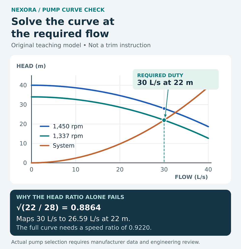
Original illustrative curve model. The corrected system curve and reduced-speed pump curve meet at 30 L/s and 22 m. A real impeller trim requires manufacturer performance data.
4. Compare the options across the actual duty range
A manufacturer-supported trim is worth investigating where the required duty has permanently reduced and the pump spends much of its time near one operating condition. Review replacement-impeller availability and future capacity before removing material. Restoring the original duty may require another impeller rather than a controls adjustment.
A variable-frequency drive offers operating flexibility when demand changes. Its usefulness still depends on an approved motor and drive combination, the control sequence and the pump’s permitted operating envelope. Evaluate maximum-demand operation as carefully as the reduced duty. Lower speed is not permission to run indefinitely at an unsupported flow.
The options can also be combined. A modest trim may improve a poor original selection while a drive handles variable demand. Compare that arrangement against keeping the original impeller, replacing the pump or correcting an erroneous control setpoint. The lowest first cost does not necessarily produce the best operating result.
5. Keep the energy comparison honest
At 30 L/s and 28 m, assume water density of 1,000 kg/m³ and pump efficiency of 76%. Shaft power is ρgQH/η = 10.84 kW. At the target 30 L/s and 22 m, the same assumed efficiency gives 8.52 kW. If the manufacturer instead predicts 70% efficiency for a proposed trim at that duty, shaft power becomes 9.25 kW.
That sensitivity calculation shows why identical flow and head do not guarantee identical input power. These are shaft values, excluding motor and drive losses. Do not convert the difference into annual savings without an operating-hours distribution, measured baseline and credible performance at each duty. The cube of a speed ratio is not a substitute for that review when the operating points are not corresponding points.
6. Ask for a reviewable modification package
Identify the pump, existing impeller diameter, verified speed and measured operating points.
Document the reason for the lower duty and which restrictions or control settings will change.
Obtain revised head, efficiency, power and NPSH-required data for the proposed configuration.
Confirm allowed flow and speed ranges, available NPSH margin, motor loading and pressure ratings.
Agree a commissioning test covering required flow, head, vibration and operating stability.
Have the responsible engineer and pump manufacturer approve the modification before machining or changing operating limits. The calculation above is a decision aid, not authorization to alter installed equipment.
For the hydraulic starting point, see Chilled Water Pump Head Calculation Explained.
To bring more structure to your next chilled-water design review, explore Nexora’s paid Chilled Water System Design Handbook.



Comments