Rectangular Duct Diameter: Hydraulic or Equal-Friction Equivalent?

One duct, two useful diameters
A rectangular duct can have a hydraulic diameter of 436 mm and an equal-friction equivalent diameter of 520 mm without either result being wrong. The numbers answer different questions. Errors appear when a calculation takes the diameter from one method and the velocity or friction factor from another.
This matters when reviewing a spreadsheet, converting a round duct layout to fit a shallow ceiling, or checking a pressure-loss calculation supplied by a contractor. Before changing the duct size, identify what each diameter field means and which geometry the calculation actually uses.
Choose the relationship you need
ASHRAE’s duct-design chapter distinguishes hydraulic diameter from the circular equivalent used for equal airflow, frictional resistance and length. For a rectangle with internal dimensions a and b, hydraulic diameter is Dh = 4A/P = 2ab/(a + b). It combines the actual cross-sectional area A and wetted perimeter P.
The commonly used equal-friction relationship is De = 1.30 × (ab)^0.625/(a + b)^0.25. Use the same length unit for both sides and the resulting diameter. De identifies an equivalent round duct for a friction-sizing comparison at the same airflow. It does not state that the rectangle and circle have equal area.
A hydraulic-diameter Darcy–Weisbach calculation uses the rectangle’s actual mean velocity with Dh. An equivalent-round calculation uses De and the equivalent circle’s velocity within the round-duct friction method. Both routes need a compatible friction-factor calculation and consistent roughness and air properties. Do not splice their inputs together.
Worked geometry: 800 × 300 mm at 1.20 m³/s
Assume clear internal dimensions of 0.800 m by 0.300 m and an actual operating airflow of 1.20 m³/s. The flow area is 0.240 m², the perimeter is 2.20 m, and the mean velocity is 1.20/0.240 = 5.00 m/s. These dimensions exclude any internal liner thickness.
The hydraulic diameter is 4 × 0.240/2.20 = 0.4364 m. The equal-friction equivalent diameter is 1.30 × (0.800 × 0.300)^0.625/(0.800 + 0.300)^0.25 = 0.5203 m. The approximately 84 mm difference is an expected consequence of their definitions.
A real 520.3 mm round duct would have an area of about 0.2126 m² and a velocity of about 5.64 m/s at this airflow. The rectangular duct still carries air at 5.00 m/s. Use that actual rectangular velocity when assessing its velocity limit or any fitting coefficient referenced to this section.
A spreadsheet error that more than doubles the result
For an original friction example, assume a 20 m straight section, density 1.20 kg/m³ and Darcy friction factor fD = 0.020. The friction factor is an explicit illustrative input; a design calculation should determine it from Reynolds number and relative roughness using a suitable correlation.
The EnergyPlus Engineering Reference also sets out the hydraulic-diameter Darcy–Weisbach pressure-loss form. The actual velocity pressure is ρV²/2 = 1.20 × 5.00²/2 = 15.0 Pa. Applying the hydraulic-diameter method gives Δpf = fD × (L/Dh) × ρV²/2 = 0.020 × (20/0.4364) × 15.0 = 13.75 Pa. This excludes fittings, leakage and equipment losses.
Now suppose the spreadsheet treats Dh as the diameter of a real circle. It replaces the 0.240 m² rectangular area with πDh²/4 = 0.1495 m², raising the calculated velocity to 8.02 m/s. Its velocity pressure becomes 38.63 Pa and, holding the same illustrative friction factor, its straight-duct loss becomes 35.41 Pa.
That result is about 158% higher than the consistent calculation. The mistake is the invented circular area, not the use of hydraulic diameter itself. Recalculating a friction factor cannot repair an incorrect geometry boundary. Check the area and velocity formulas before debating small differences between friction correlations.
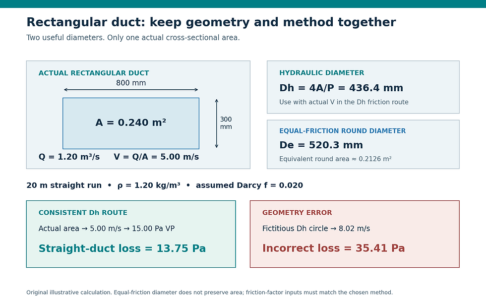
Original geometry and friction example. The calculation must retain the actual rectangular area when using the hydraulic-diameter route.
Audit the method rather than the column label
In the calculation file, trace one duct row from dimensions to area, velocity, Reynolds number, diameter and friction factor. Confirm whether the friction factor is Darcy or Fanning; the Darcy value is four times the Fanning value. A label saying “friction factor” without a convention leaves a serious review gap.
For the example, assuming dynamic viscosity 1.81 × 10⁻⁵ Pa·s gives Re = ρVDh/μ ≈ 145,000. This supports treating the flow as turbulent, but does not select the wall roughness. Record the material and construction assumption, and distinguish an absolute roughness in metres from relative roughness ε/Dh.
Keep a separate actual-area velocity column even when the sizing tool uses an equivalent-round method. Verify the reference area for each fitting coefficient. A change in rectangular aspect ratio can alter installation space, perimeter, construction requirements and fitting geometry even when a friction-equivalent round size stays similar.
What to put on the reviewed calculation
Report internal width and height, airflow basis, actual area and velocity, calculation method, diameter definition, roughness, fluid properties and straight-duct loss. Add fittings and equipment at their own documented boundaries. Retain one hand-check row so a later reviewer can reconstruct the method without reverse-engineering the workbook.
Use these correlations within their intended duct-flow application. Extreme aspect ratios, unusual linings, developing flow and laminar or transitional conditions deserve a more specific treatment. The useful acceptance question is whether the method is suitable and internally consistent, rather than whether every tool displays the same diameter.
Sources and further reading
Continue your engineering workflow
The paid HVAC Duct Pressure Loss Design Suite is an Excel workbook with rectangular-duct hydraulic diameter, Reynolds number, Darcy–Weisbach losses and critical-path reporting to help organize a traceable design check.



Comments