Supply–Return Airflow Tracking: Why a Fixed Offset Does Not Guarantee Building Pressure
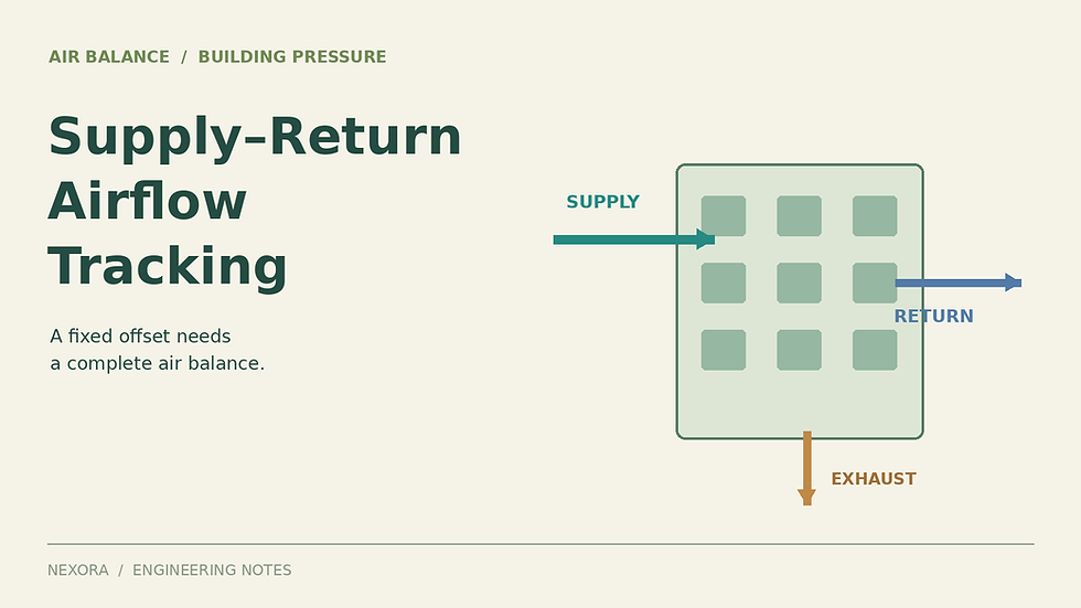
A return fan that tracks supply airflow can hold the programmed difference exactly while the building becomes harder to pressurize. The missing information may be local exhaust, an open exterior door, a changing pressure zone or measurement bias. Start with a clearly drawn air balance, then check what the controller actually measures and controls.
1. Define the control boundary
For the occupied-space boundary, define Q_S as supply entering, Q_R as return leaving toward the AHU, Q_E as separate local exhaust, and Q_X as net outward envelope flow. With no other transfer paths and steady storage, Q_X = Q_S − Q_R − Q_E. Positive Q_X means net exfiltration; negative Q_X means net infiltration.
This volumetric form assumes all flows use the same reference density. Real supply and return air can have different temperatures and densities. Use a mass balance or consistently density-normalized volumes when that difference is material. Also reconcile duct leakage and transfer air before comparing an AHU airflow station with the flow actually reaching the occupied space.
A return fan upstream of the recirculation/relief split handles both air that will be recirculated and air that will be discharged. Do not subtract the central relief flow again from this occupied-space balance. For a whole-building boundary, instead compare outdoor intake with all outdoor discharge paths. The two balances are consistent when the same physical paths are counted once.
ASHRAE’s controls chapter distinguishes indirect airflow-differential control from direct building-pressure measurement. Neither a fan-speed percentage nor an airflow offset is itself an indoor–outdoor pressure reading.
2. Calculate the surplus after local exhaust
Assume an original, simplified example with density-normalized supply airflow of 10.00 m³/s and return airflow of 9.20 m³/s. The tracking offset is therefore 0.80 m³/s. Separate exhaust removes 0.45 m³/s. Assume no other air transfer, no duct leakage across the boundary, stable doors and a single pressure zone.
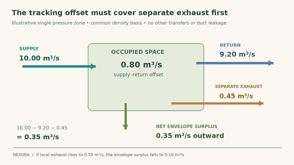
Illustrative occupied-space balance on a common density basis. Central relief downstream of the measured return is not subtracted again from this boundary.
Net outward envelope flow is 10.00 − 9.20 − 0.45 = 0.35 m³/s.
Now let separate exhaust increase to 0.70 m³/s while the tracking offset remains 0.80 m³/s. Envelope surplus falls to 0.10 m³/s.
If separate exhaust reaches 0.95 m³/s, the net balance becomes −0.15 m³/s. The same programmed offset now requires inward envelope flow under the simplified assumptions.
The return-airflow controller can be operating correctly in all three cases. The fault is expecting one fixed difference to cover every exhaust mode. Trane’s building-pressurization newsletter highlights the importance of stable local exhaust and accurate flow sensors for tracking applications.
3. Convert surplus to pressure only with a leakage model
For a deliberately simple illustration, assume a fixed envelope with Q_X = C × Δp^n for outward flow, an exponent n = 0.65 and a measured reference point of 0.35 m³/s at 5.0 Pa. Ignore wind, stack effect, bidirectional flow and interzone pressure differences. The 5.0 Pa value is an example reference point, not a recommended setpoint or compliance threshold.
Under those assumptions, Δp = 5.0 × (Q_X/0.35)^(1/0.65). Reducing surplus to 0.10 m³/s gives approximately 0.73 Pa. A 71% reduction in surplus produces about an 85% reduction in pressure in this particular model. Changing the building leakage or opening a door changes the relationship again.
NIST’s CONTAM documentation describes power-law flow elements for cracks and openings. Such a relationship is useful for sensitivity analysis, but the coefficient and exponent must represent the actual flow path. NIST also describes multizone pressure calculations driven by fans, wind and buoyancy. One pressure number cannot describe every floor and facade of a real building.
4. Check whether measurement error can consume the offset
Assume, solely for a bounding example, that each airflow indication can differ from actual flow by up to 3% of its indicated value. The supply uncertainty bound is then 0.30 m³/s, and the return bound is 0.276 m³/s. If the supply indication is high while return indication is low, actual flows could be 9.70 and 9.476 m³/s.
Their actual difference is only 0.224 m³/s. After the assumed 0.45 m³/s local exhaust, net envelope flow is −0.226 m³/s even though the screen shows the target 0.80 m³/s offset. Opposite error directions would give +0.926 m³/s net outward flow. These are bounding scenarios, not probabilities or a claim about a particular sensor.
Calibrate and verify each airflow station over its operating range. Check installation requirements, signal scaling, density basis, low-flow limitations and the independent reference method. A good full-flow comparison does not establish the accuracy of a small difference at minimum operation. Improving only one station may leave the other station’s bias dominant.
5. Test the operating modes and control responsibilities
List which exhaust fans, air handlers and pressure zones operate in occupied, warm-up, cooldown and unoccupied modes. Include transfers to adjacent zones.
Measure supply, return, separate exhaust and indoor–outdoor pressure together at several stable load points. Record door state, wind conditions and outdoor temperature.
Trend outdoor-air, return and relief damper commands alongside the airflow and pressure readings. Confirm which actuator controls each variable in the approved sequence.
Test expected exhaust changes and economizer operation within the authorized commissioning procedure. Check minimum-speed and maximum-flow limits before changing controller gains.
Document where the pressure is sensed and how filtering is applied. A sensor exposed to local airflow or wind can produce a misleading control signal.
Mode-dependent offsets need explicit design logic. ASHRAE Addendum f to Guideline 36-2018 discusses problems with carrying an unchanged tracking offset into different occupancy modes. It is a historical published example of this issue, not a substitute for the project’s adopted sequence or current applicable requirements.
6. Make the next correction specific
If airflow tracking is accurate but pressure changes with exhaust, address the mode-dependent balance. If displayed flows disagree with independent measurements, fix the measurement chain first. If pressure changes with weather or door operation, assess reference locations, envelope behavior and pressure-zone boundaries. Any move to direct pressure control must coordinate the return fan and relief arrangement to avoid competing loops.
Keep ventilation verification separate: a supply–return offset does not directly establish the required outdoor intake. For wider commissioning reference, review the paid Air Balancing (TAB) Toolkit: Excel Workbook + Pocket Field Handbook. Base acceptance on the approved operating sequence and recorded measurements.



Comments