VAV Minimum Pressure and Low-Flow Signal: Two Separate Checks
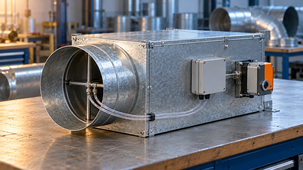
Why a healthy pressure reading can hide a low-flow problem
A VAV controller shows a steady minimum airflow, the duct has ample static pressure, and the room still feels overcooled. Raising the air-handler pressure setpoint may make the symptom worse. The first diagnostic step is to identify which pressure was measured and what that measurement proves.
Two different pressure differences matter. The terminal needs sufficient operating pressure to deliver the requested airflow through its air path. Its airflow pickup also needs a measurable signal that the transducer and controller can resolve accurately. A satisfactory result for the first check does not establish the second.
Draw the pressure boundaries before adding allowances
Carrier’s air-terminal product data describes the minimum static-pressure difference across a terminal, with the damper open, and the additional inlet pressure needed for downstream ducts and outlets. Use the selected unit’s current performance data and stated pressure boundary; labels such as “minimum inlet pressure” are not enough on their own.
For a deliberately simplified static-pressure example at a specified flow, assume the terminal requires 60 Pa between its documented inlet and discharge reference points. Its downstream distribution requires 75 Pa relative to the served room. The inlet requirement is then 60 + 75 = 135 Pa relative to that same room, before any explicitly justified operating allowance.
If measured inlet static is 180 Pa and discharge static is 75 Pa on the same reference, the terminal has 105 Pa available across it. That is 45 Pa above the assumed 60 Pa requirement at this duty. Do not add downstream resistance twice. If the catalog instead provides total-pressure loss, account for inlet and outlet velocity pressures consistently before making this comparison.
The small signal at the airflow pickup
Johnson Controls’ FlowStar guidance explains why oversized terminals can create weak pressure signals at minimum airflow, and why sensor amplification and controller range need attention. An airflow pickup’s differential signal is related to velocity. It is separate from the inlet-to-discharge pressure difference that drives air through the unit.
For an original example, assume a particular pickup and its configured coefficient obey Q = C√Δps over the verified operating range. Let Q be actual airflow in m³/s and Δps be the pickup differential in Pa. A confirmed point of 0.400 m³/s at 80.0 Pa gives C = 0.400/√80 = 0.04472 m³/(s·√Pa).
At 20% of that airflow, Q = 0.080 m³/s, the signal is (0.080/0.04472)² = 3.20 Pa. At 10%, or 0.040 m³/s, it falls to 0.80 Pa. Reducing airflow by half reduces the signal to one quarter. The earlier 105 Pa across the terminal cannot be substituted into this pickup equation.
Quantify the consequence of an offset
Suppose the pressure reading has an illustrative ±0.50 Pa offset. This is a sensitivity test, not a claim about a particular controller’s specification. At the 3.20 Pa signal, the indicated airflow ranges from C√2.70 = 0.0735 m³/s to C√3.70 = 0.0860 m³/s. The errors are approximately −8.1% and +7.5%.
At the 0.80 Pa signal, the same offset produces 0.0245 to 0.0510 m³/s, approximately −38.8% to +27.5%. An apparently small pressure error is now a large fraction of the measurement. Instrument resolution, zero drift, pickup calibration, density correction and inlet-flow distortion can contribute additional errors.
A practical selection check therefore starts with the required minimum airflow and the manufacturer’s usable measurement range for the complete pickup, transducer and controller combination. Avoid adopting a universal minimum percentage of box capacity. A controller that displays a value below its verified range has not demonstrated accurate control there.
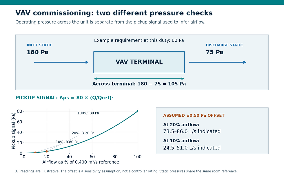
Two independent checks: pressure available to the terminal and differential signal available to the airflow controller. All values are illustrative.
Commission minimum and maximum as different tests
Begin with the approved airflow schedule, terminal size, pickup coefficient, controller units and operating sequence. Inspect tubing for incorrect connections, leaks, kinks and condensate. Confirm the actual inlet arrangement against the manufacturer’s installation requirements, including any straight duct, elbow or flexible-duct restrictions.
Carry out the manufacturer’s zeroing procedure under its specified conditions. For example, Trane’s Symbio 210 manual describes automatic flow-transducer calibration associated with unoccupied operation, with separate consideration for continuously occupied sites. Follow the procedure for the installed controller; do not improvise a zero while an unknown airflow is present.
At maximum demand, verify independent airflow, damper stroke and the available pressure across the correct terminal boundary. At minimum demand, compare the controller reading with an independent method suitable for that low airflow. Record the pickup differential as well as airflow. If the reference method has comparable uncertainty to the suspected error, the comparison cannot resolve the dispute.
Then vary upstream pressure within the approved test range while holding the airflow setpoint. Look for repeatability, hunting and loss of control. Restore temporary overrides afterward. A single successful reading at one inlet pressure is weaker evidence than a stable response across the conditions the terminal will actually encounter.
Make the corrective action match the evidence
If the fully open terminal cannot meet design flow and lacks its required operating pressure, investigate the pressure budget and restrictions. If pressure is adequate but minimum-flow measurement is unreliable, address pickup installation, calibration, transducer capability or terminal selection. Change the approved minimum airflow only through a design review that retains ventilation, heating and distribution requirements.
Close the test with dated readings, instrument details, stated uncertainty and the final controller settings. This provides a defensible reason for the correction and prevents a future technician from treating a sensing problem as a request for more fan pressure.
Sources and further reading
Continue your engineering workflow
The paid Air Balancing (TAB) Toolkit combines an Excel results workbook and a 20-page pocket PDF handbook for recording airflow deviations, instrument calibration status and commissioning deficiencies.



Comments