VAV Static-Pressure Reset: Commissioning a Terminal-Demand Sequence
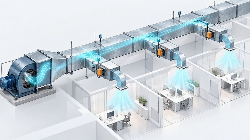
A useful VAV static-pressure reset lowers the duct-pressure target when terminals have spare control authority and raises it when verified terminal demand needs more pressure. Its success depends on trustworthy airflow and damper data, stable timing, sensible limits and commissioning. A low pressure trend by itself is not evidence of successful operation.
1. Keep the two control loops distinct
The fast loop adjusts supply-fan speed to maintain measured duct static pressure at its current setpoint. The slower supervisory loop changes that setpoint in response to terminal demand. Trying to make both loops respond aggressively to every damper movement invites interaction. Establish stable pressure control before enabling automatic reset.
ASHRAE describes resetting the pressure target as VAV terminals unload, while its Guideline 36 material documents request-based trim-and-respond logic. Use the project-specified edition and approved sequence for compliance; the teaching sequence below is intentionally simplified. References: ASHRAE Air Handling and Distribution and Guideline 36-2021 Addendum s.
Duct static reset does not calculate the building’s minimum outdoor-air requirement or replace its ventilation controls. Keep the approved outdoor-air, building-pressure and terminal-minimum sequences active and verify them across the reset range. The related minimum outdoor air at VAV turndown guide deals with that separate airflow obligation.
2. Decide which terminal information is credible
For each terminal, expose airflow setpoint, measured airflow, damper command, actual position feedback where available, operating mode, communication age and request status. A command of 100% does not prove the blade is open. An airflow reading of zero may indicate a sensor or tubing fault. Compare both against physical operation during checkout.
Use the design and TAB records to identify difficult branches and terminals that matter to pressure control. Then investigate persistent demand. Trane’s Engineers Newsletter on airside reset discusses rogue-zone causes including undersized boxes and obstructed supply paths. Increasing system pressure can mask these defects while other boxes throttle harder.
Request exclusions need an owner, reason and review date. Do not silently remove a genuinely pressure-starved occupied zone to make the trend look better. Safety-critical or process-critical applications need their own engineered priority logic and operating constraints, beyond this comfort-system example.
3. Define a bounded illustrative sequence
Consider a fictional comfort AHU serving 12 pressure-independent VAV terminals. Commissioned limits are assumed to be 100–300 Pa at one defined duct sensor, with an initial target of 220 Pa. These numbers are teaching inputs, not recommended defaults or universal code settings. The designer must establish actual limits from ductwork, fan capability, terminal performance and functional tests.
Enable reset only after fan proof and a 10-minute startup stabilization period. Run the fan pressure loop continuously; evaluate the supervisory reset every two minutes.
For this example, a valid terminal sends one request when its damper command exceeds 90% and measured airflow remains below 95% of its positive airflow setpoint for 60 seconds. Retain the request until airflow reaches 98% of setpoint or damper command falls below 85%. These deliberate hysteresis bands are illustrative.
Let R be the number of active valid requests. Ignore no requests in this example. If R = 0, lower the pressure setpoint by 10 Pa. If R is positive, increase it by the smaller of 10R Pa and 30 Pa. Never apply both changes in one interval.
Clamp the resulting setpoint between 100 and 300 Pa. If requests persist at the maximum, alarm and diagnose; do not automatically expand the upper limit.
If required terminal-data coverage is lost while duct-pressure feedback remains valid, suspend reset and invoke the approved fallback, such as a previously commissioned fixed pressure target. If duct-pressure feedback is invalid, use the engineered sensor-failure sequence and protective response; a fixed target cannot restore missing feedback. Define coverage, alarm delay and recovery explicitly.
Independent fan interlocks and protective limits still take priority. Do not use this simplified request rule where process safety, laboratory airflow tracking or life-safety operation needs another sequence. Implementing this example also does not establish Guideline 36 compliance.
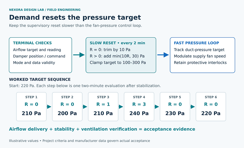
Illustrative sequence only: terminal requests adjust a bounded duct-pressure setpoint, while the inner fan loop tracks that target. The sample steps follow the article’s explicit arithmetic.
4. Calculate the trend you expect to see
Start at 220 Pa after stabilization. For successive two-minute evaluations, suppose R is 0, 0, 1, 3, 0 and 0. The setpoints become 210, 200, 210, 240, 230 and 220 Pa. The third step adds 10 Pa; the fourth adds the capped 30 Pa. At the assumed 100 Pa floor, another zero-request interval leaves the setpoint at 100 Pa.
If the measured pressure tracks these setpoints but a terminal stays below airflow target, inspect the terminal and branch. If pressure cannot reach the target, investigate fan limitation, control tuning, sensor error or system resistance. Those are different failure paths, so trend the requested setpoint, measured pressure and fan command together.
Do not claim fan-energy savings from the setpoint reduction alone. Total fan pressure includes losses outside the sensor’s controlled duct section, and flow and efficiency can change. Compare measured electrical input at matched operating conditions or use an appropriate normalized assessment; retain comfort and ventilation evidence alongside it.
5. Commission by introducing known disturbances
Calibrate the duct-pressure sensor against a suitable reference and check tubing, zero and pressure pickup arrangement. Document the exact measurement location.
Stroke representative dampers and verify airflow readings against TAB measurements. Include the critical branch and terminals with prior complaints.
At a controlled low-load condition, demonstrate that zero requests trim the target without losing required terminal flow. Observe actuator settling before shortening timing.
Increase an approved terminal airflow target or otherwise create a controlled demand. Confirm request generation, the response increment and recovery; then restore the original setting.
Simulate stale communication and sensor failure through the approved test method. Confirm the alarm, fallback and recovery. Check startup, shutdown and restart so a retained low target does not create an unexpected delay.
Repeat at several representative loads. Coordinate supply-air-temperature reset because changing supply temperature can change terminal airflow demand.
6. Accept airflow delivery and stability together
Terminal airflow tracks the approved targets within project test tolerances throughout representative operation.
The pressure loop settles adequately between reset actions, without repeated limit cycling.
The lower and upper bounds, maximum response and startup delay are demonstrated.
Outdoor-air delivery and building-pressure control remain acceptable across fan turndown.
Persistent requests have a documented cause; exclusions and overrides are visible and reviewed.
The operator can see requests, data validity, current mode, fallback status and the reason for each reset action.
The handover should include the actual tuned parameters and a short annotated trend, not only a controls screenshot. Recheck after duct changes, tenant fit-outs or terminal replacement. For the pressure limits behind the sequence, see duct pressure class versus fan ESP.
Continue your engineering workflow
For the wider duct-design and pressure-loss workflow, explore the Nexora HVAC Duct Design and Sizing Handbook. Get the complete handbook.


Comments