Ventilation Louver Selection: Free Area, Pressure Loss and Rain Performance

Select a ventilation louver by checking the actual opening available to airflow, the resistance at the required duty and the rain performance relevant to the exposure. Gross opening dimensions alone cannot establish whether an intake will deliver its design airflow or manage water acceptably. A useful submittal connects the architectural opening to a specific louver model, size, assembly and operating point.
This review method is intended for building-services designers and site teams. The calculations below are original hypothetical examples, not published ratings for a particular product. Final selection needs the manufacturer’s current data, the project criteria and coordinated architectural and structural details.
1. Keep gross, free and core areas separate
Gross face area is the overall width multiplied by height on the dimensional basis being used. Free area is the open passage area remaining after the louver’s frame and blades are accounted for. Obtain it from the selected product’s table or selection output at the actual dimensions. A percentage advertised for a reference-size louver should not automatically be applied to every size or multi-section assembly.
Core area is another reference area that can appear in wind-driven-rain data. It is not interchangeable with free area. Record the area definition beside every velocity. Greenheck’s louver performance introduction explains the free-area relationship and why free area alone does not determine resistance.
Gross-face velocity = airflow ÷ gross face area.
Free-area velocity = airflow ÷ manufacturer’s free area.
Core velocity = airflow ÷ the core area defined for the relevant rating.
Convert airflow to m³/s before dividing by an area in m² to obtain m/s.
2. Worked example: one opening, two different velocities
Assume an intake requires 3.60 m³/s through a 2.00 m × 1.50 m louver. For this example, the selected size has a manufacturer-confirmed free area of 1.35 m². The gross area is 3.00 m², giving a free-area ratio of 1.35 ÷ 3.00 = 45%.
Gross-face velocity: 3.60 ÷ 3.00 = 1.20 m/s.
Free-area velocity: 3.60 ÷ 1.35 = 2.67 m/s.
Read any free-area-based pressure or water-penetration data at 2.67 m/s, using the specified intake direction.
Now suppose an architectural substitution has the same overall dimensions but only 1.20 m² of verified free area. Its free-area velocity becomes 3.60 ÷ 1.20 = 3.00 m/s, a 12.5% increase. The facade opening has not changed, yet the relevant operating point has. Recheck the substitute’s own resistance and rain data; matching the original dimensions is insufficient.
If more area is needed, ask for a fresh selection at the proposed revised dimensions. Wider frames, intermediate mullions, blade supports or a different aspect ratio can change the free-area ratio. Treat 45% as a fact about this hypothetical selection, not a scaling rule.
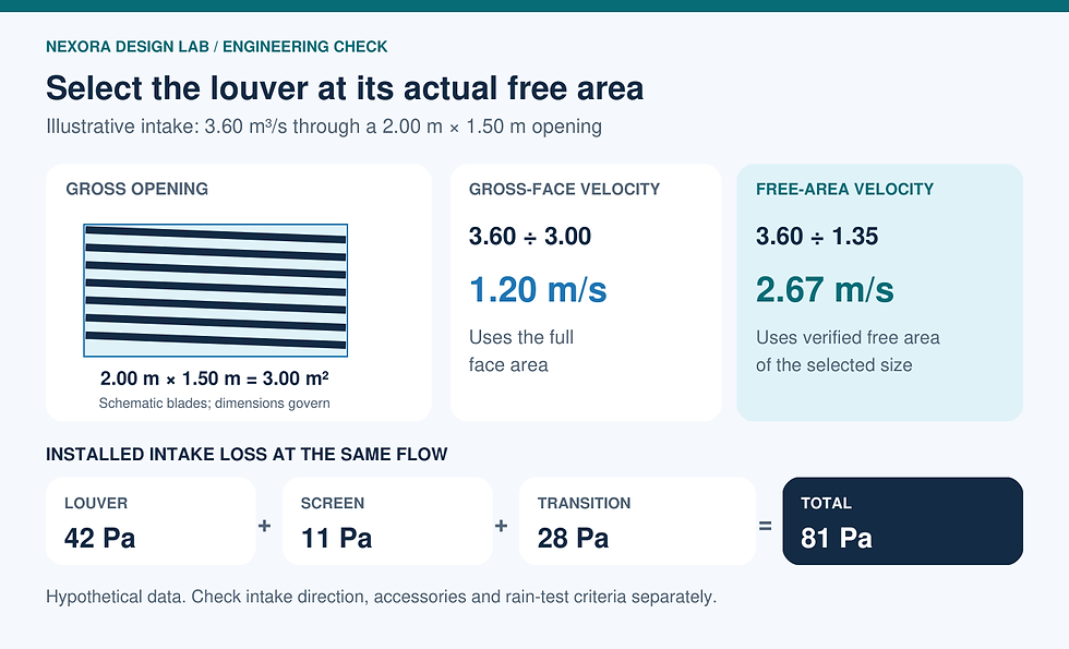
Original illustrative selection check. Free area and all pressure losses are hypothetical; use verified data for the actual product and assembly.
3. Read pressure loss and rain ratings independently
A pressure curve needs an airflow direction, air-density basis and reference velocity. Confirm whether screens and other accessories are included. As an example of how published data are organized, Greenheck’s EHH-601 submittal provides separate area tables, intake/exhaust resistance curves and water-performance information. Its wind-driven-rain table identifies both core and free-area velocities.
Conventional water-penetration testing and wind-driven-rain testing address different conditions. A beginning-point result from one test should not be presented as proof of performance under the other. Compare the required wind and rainfall conditions, ventilation velocity, classification and any installation conditions. An AMCA seal also needs its certified rating scope checked; AMCA’s air-control-device rating manual sets out separate louver rating requirements.
Do not turn a catalogue maximum into an operating target without reviewing the project’s exposure and water-management tolerance. A plantroom intake, an intake beside moisture-sensitive equipment and an exposed coastal opening may need different solutions. Drainage provisions remain part of the design even when a strong rain-rejection rating is specified.
4. Build the installed intake pressure budget
Continue the hypothetical 3.60 m³/s example. Suppose verified selections at that duty give 42 Pa for the louver, 11 Pa for a separately assessed screen and 28 Pa for the plenum transition. The combined allowance is 42 + 11 + 28 = 81 Pa. If 130 Pa was allocated to this intake assembly within the complete fan pressure budget, 49 Pa remains within that allocation.
This is a bookkeeping check. It assumes the boundaries are compatible, the losses are not already included in another component selection and the assembly layout does not introduce an unaccounted system effect. The remaining 49 Pa is not permission to add restrictions casually. Reconcile the full fan-to-terminal path and confirm the fan operating point.
For a preliminary sensitivity check only, raising flow by 25% through unchanged geometry would raise an approximately quadratic 81 Pa loss to about 81 × 1.25² = 127 Pa. This suggests little allowance remains. It does not replace new manufacturer selections, and it predicts neither water rejection nor rain classification.
5. Check the assembly that will actually be installed
Screens and concealed supports deserve explicit coordination. Ruskin’s louver design considerations discusses screen resistance, shaped louvers, multi-section construction and the extra depth that rear blade supports can require. A clean product curve cannot resolve a clash with a damper, blocked drainage path or crowded plenum.
Confirm the opening schedule, actual product dimensions and installation clearances against the approved facade detail.
List bird or insect screens, filters, dampers, blank-off panels and their pressure-loss boundaries.
Check mullions, supports and adjacent structure for airflow obstruction and maintenance access.
Coordinate sill pans, drainage, seals and discharge paths with the manufacturer and envelope designer.
Review proximity to exhausts and contamination sources using the applicable project requirements.
At handover, record airflow, fan condition, screen condition and intake pressure readings at defined measurement locations.
A review-ready louver submittal
The acceptance record should contain the required airflow, selected model and dimensions, actual free area, operating velocities, relevant pressure data, rain-test basis, accessories and installation details. Close discrepancies before the opening is built. Site airflow measurements can verify installed duty, but they do not recreate laboratory rain testing or certify performance in every storm.
For connected checks, see low exhaust airflow and the makeup-air path and fan operating-point verification.
Continue your engineering workflow
For the wider ventilation airflow and fan-selection workflow, explore the Nexora Ventilation Exhaust Design Practical Engineering Handbook. Get the complete handbook.


Comments