Chilled-Water Temperature Reset: Humidity and Coil-Capacity Limits
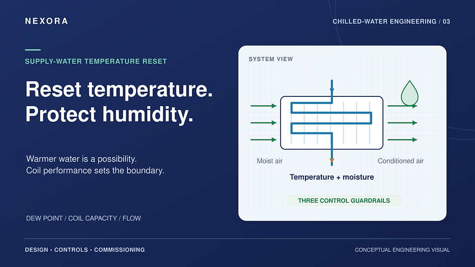
A mild afternoon can leave a building with little sensible cooling demand and plenty of moisture to remove. Raising chilled-water supply temperature on outdoor dry-bulb alone can therefore create a humidity problem before anyone complains about room temperature. A useful reset sequence needs permission from the loads it serves.
Start with the moisture limit
Warmer supply water can reduce compressor lift and power, but it also warms the cooling-coil surface. Moisture condenses only where that surface is below the entering-air dew point. Water temperature alone does not establish the leaving-air dew point or the amount of moisture removed.
Check zone humidity or dew-point targets, ventilation latent load and required leaving-air conditions. A satisfied room thermostat does not prove adequate dehumidification, as Johnson Controls’ dehumidification guidance illustrates. Give a valid humidity demand priority over an upward reset.
Find the limiting coil
Recheck coil selections at the proposed warmer water temperature, actual airflow and available water flow. Confirm both sensible and latent capacity. A coil already operating with an open valve and unmet leaving-air temperature has little room for warmer water.
Check valve feedback and sensor accuracy before letting one persistent request govern the whole plant. Poor balancing, fouling or inadequate differential pressure can imitate a genuine temperature requirement.
Calculate the flow consequence
For a water-only illustration, use density ≈ 1,000 kg/m³ and specific heat ≈ 4.18 kJ/(kg·K):
Q (kW) ≈ 4.18 × V̇ (L/s) × ΔT (K)
At 418 kW and a 5 K return-to-supply difference, flow is 418 ÷ (4.18 × 5) = 20 L/s. If that difference falls to 3 K at the same load, required flow becomes 33.3 L/s, about 67% higher.
This is a sensitivity check, not a prediction that every reset produces a 3 K difference. Coil performance determines the actual result. Check pump capacity, valve authority and equipment flow limits; use actual fluid properties for glycol.

Conceptual reset checks. The flow example assumes unchanged load and a hypothetical reduction in ΔT.
Make the reset slow and reversible
Define project-specific minimum and maximum supply temperatures. Trim upward gradually only while critical coils and humidity targets remain satisfied; respond downward when verified demand requires colder water. Include a deadband and persistence time so brief disturbances do not cause hunting.
Coordinate temperature reset with pump differential-pressure reset and chiller staging. Johnson Controls’ plant-reset sequence holds its reset value during staging transitions. Document a conservative fallback for failed sensors or lost communications, and retain all manufacturer protection limits.
Prove the result in trends
Trend supply/return temperatures, flow, critical valves, leaving-air conditions, humidity and total plant electrical power. Compare similar load and weather periods, including humid low-load operation. A lower compressor reading is insufficient if pumping or air-side energy rises. Keep the reset only within the tested comfort, capacity and equipment envelope.
Connect controls to the wider design
For related hydraulic symptoms, see Nexora’s low delta-T guide. Nexora’s Chilled Water System Design Handbook covers coils, BMS sequences and commissioning within a complete design workflow. Explore the handbook to connect reset decisions with the rest of the system.


Comments