Chilled-Water Thermal Energy Storage: Sizing a Stratified Tank for Peak Shifting

Select a chilled-water storage tank against cooling energy, discharge power and delivery temperature. Sufficient kilowatt-hours will not compensate for a warm outlet, inadequate diffuser flow capacity or a missed recharge window.
This guide addresses stratified sensible storage for multi-hour peak shifting. A buffer tank selected for chiller short-cycle protection uses minimum run time and permissible temperature swing. Meeting that minimum system-volume requirement does not establish peak-shifting capacity.
Define the temperature boundary first
At ordinary chilled-water temperatures above water's maximum-density region, colder water is denser and occupies the bottom of a stratified tank. Warm return water occupies the top. During discharge, cold water leaves the bottom while warm return water enters the top. Charging reverses those flows. The U.S. Department of Energy thermal-storage fact sheet describes this sensible-storage arrangement and the separating temperature-transition layer, or thermocline.
Specify the cold charging temperature, expected warm-layer temperature and maximum discharge temperature, including coil and humidity requirements. A tank with energy remaining may already be too warm for a critical coil.
Specify whether the tank is directly connected to the building water or separated by a heat exchanger. With separation, calculate storage-side temperatures from the exchanger's approach temperatures at the relevant flow and fouling condition. Using the building's full supply-to-return difference for tank sizing can overstate storage capacity.
Separate energy from power
Use a time-resolved load profile and chiller schedule. For each interval, calculate the storage contribution after the permitted chiller output, then integrate over the discharge window:
E_required = Σ(P_storage × Δt)
With P_storage in kW of cooling and Δt in hours, E_required is kWh of cooling. These are thermal quantities. They do not directly state electrical demand reduction or electricity savings.
Also record the largest required P_storage. A four-hour duty of 600 kW has the same energy as a two-hour duty of 1200 kW, but requires different flow and delivery hardware. Use sufficiently short load intervals to capture the peaks that govern pumps, valves, diffusers and any heat exchanger.
For an initial sensible-water estimate:
E_useful = ρcₚVΔT fᵤ / 3600
Here ρ is kg/m³, cₚ is kJ/(kg·K), V is gross stored-water volume in m³ and ΔT is K. The divisor converts kJ to kWh. The factor fᵤ represents the fraction of the ideal energy available before the specified outlet-temperature limit is reached. It is a project-specific usable-capacity factor, not a universal efficiency.
Example 1: size the water volume and discharge flow
Assume a direct-connected tank must provide 600 kW for four hours. Use water at a cold temperature of 6°C and warm temperature of 14°C, giving ΔT = 8 K. For this preliminary calculation, take ρ = 1000 kg/m³ and cₚ = 4.186 kJ/(kg·K). Adopt fᵤ = 0.85 as an explicit design assumption, pending supplier validation for the outlet-temperature limit and duty profile.
The required useful energy is:
E_required = 600 × 4 = 2400 kWh
Each cubic metre ideally holds:
1000 × 4.186 × 8 / 3600 = 9.302 kWh/m³
The preliminary gross water volume is:
V = 2400 / (9.302 × 0.85) = 303.5 m³, rounded to 304 m³
This is a water-volume estimate before separately justified heat-gain allowances and operational reserve. Structural freeboard is not stored water. Clarify which unusable spaces are included in the quoted volume to avoid double-counting.
At the stated temperature difference, the required flow follows from P = ρcₚQΔT:
Q = 600 / (1000 × 4.186 × 8) = 0.01792 m³/s
Therefore the discharge duty is approximately 17.9 L/s or 64.5 m³/h. Check this flow against the complete discharge path, including diffuser performance, pump head and heat-exchanger pressure loss where applicable.
Now test a reduced return-water temperature. If the warm water is only 12°C while the cold supply remains 6°C, ΔT falls to 6 K. Assuming the same usable-capacity factor, the originally calculated tank stores about 1800 kWh, enough for only three hours at 600 kW. Maintaining 600 kW at this lower ΔT requires approximately 23.9 L/s. Low delta-T therefore challenges both storage duration and flow capacity.
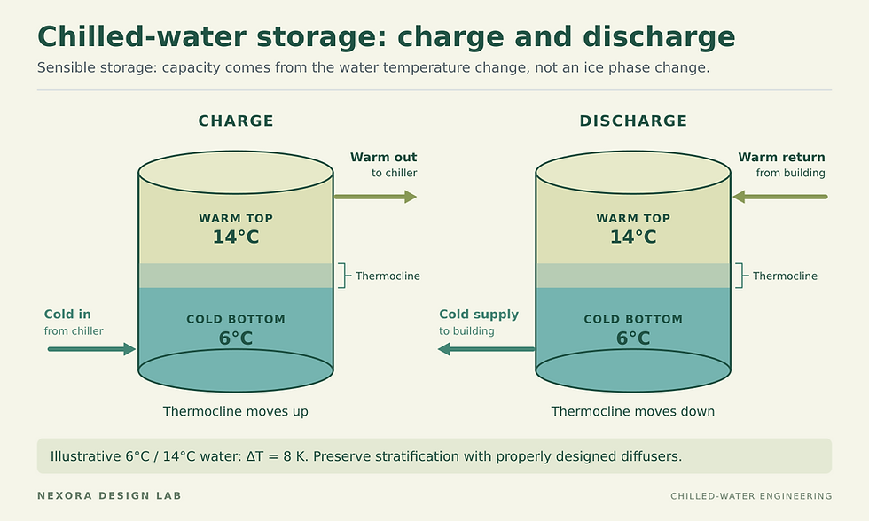
Charging and discharging flow directions for sensible chilled-water storage. An illustrative 6°C/14°C operating range gives an 8 K temperature difference; low-mixing diffuser design preserves stratification.
Protect the thermocline and specify usable capacity
The thermocline has finite thickness. Mixing and the location of the inlet and outlet hardware affect how much cooling can be delivered before the outlet becomes too warm. The International District Energy Association TES report, Appendix 1, describes stratification, the effect of the transition layer on useful tank volume, and internal diffuser arrangements.
Ask the tank supplier for a guaranteed usable thermal capacity under named conditions: initial temperature profile, charging temperature, return temperature, charge and discharge flow ranges, idle time, and discharge cutoff temperature. Include partial-charge operation if the plant will rely on it. These conditions make the quoted capacity verifiable.
Do not automatically deduct a fixed thermocline thickness and then apply a separate generic capacity reduction for the same effect. Define exactly what fᵤ includes. Keep heat gained through the tank and piping, deliberate standby reserve, and degradation caused by the proposed duty cycle visible in the calculation.
Example 2: prove the overnight charge balance
Continue with the 2400 kWh useful discharge requirement. Suppose a preliminary heat-gain assessment adds 120 kWh over the relevant daily cycle. This is an illustrative assumption requiring an insulation and operating-temperature calculation. Assume the selected operating cycle can restore the specified useful capacity by removing 2520 kWh, with no additional recharge penalty.
With a six-hour charging window:
Average cooling available for storage = (2400 + 120) / 6 = 420 kW
If the building simultaneously needs an average 300 kW, the chillers must provide at least 420 + 300 = 720 kW of cooling on average during that window. Check their available output at the actual charging temperature and condenser conditions, rather than relying on a nameplate rating at another condition.
The average is an energy check, not a complete dispatch schedule. For every interval, verify that available chiller output minus building load can meet the required charge rate. Enforce chiller minimum-flow and minimum-load limits, tank charge-flow limits and the selected reserve. A plant that meets the six-hour average can still miss completion if capacity is unavailable during a crucial part of the window.
The 0.85 usable-capacity factor has already increased the physical volume in Example 1. Do not divide the daily recharge energy by 0.85 again as though it were an electrical or cycle efficiency. If the real temperature profile requires additional cooling to restore the tank, calculate that from the profile and include it explicitly.
Controls and acceptance tests complete the sizing
Track temperatures at several tank heights along with tank inlet and outlet temperatures and flow. A single average temperature cannot show where the thermocline lies or whether the next hour's discharge will meet the supply limit. EnergyPlus's stratified-storage documentation illustrates a multi-node approach accounting for fluid flow, conduction and mixing; a project model still needs appropriate inputs and validation.
Define the response at the temperature cutoff: increase chiller contribution, curtail discharge or use an agreed reserve. Coordinate this before commissioning to protect comfort and process limits.
For acceptance, measure delivered cooling by integrating flow and the measured return-to-supply temperature difference over the agreed test period. Confirm delivery temperature throughout, peak discharge power, usable kWh and completion of the subsequent charge. Record initial and final temperature profiles and account for the test's actual heat gains.
The final selection should therefore state water volume, usable kWh, charge and discharge kW, temperature limits and the validated operating sequence. Nexora's Chilled Water System Design Handbook provides a broader design reference alongside this tank-specific sizing process.


Comments