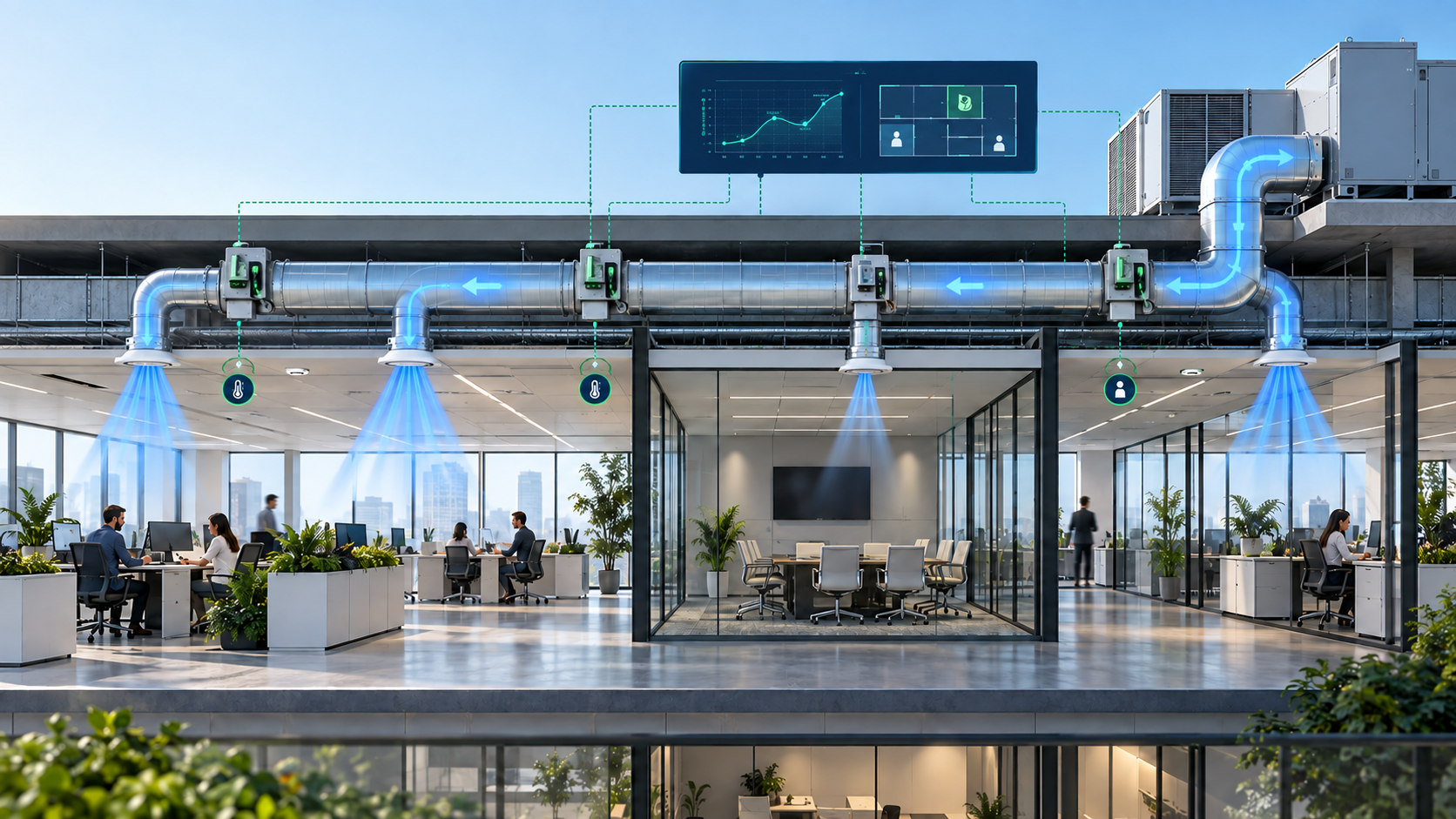
Can Smart Dampers and AI Cut HVAC Energy Use by 30%?
Yes—but not in every building and not from smart dampers alone. A properly designed system combining room sensors, modulating dampers, variable-speed fans, intelligent sequences and continuous commissioning can reduce HVAC energy use substantially. The real objective is to match airflow, cooling capacity and operating time to actual demand in each space.
Why One Room Is Hot and Another Is Cold
Many buildings are controlled as if every room has the same load at the same time. Real loads change with solar exposure, occupancy, equipment, orientation, door opening and outdoor weather.
Lowering the central thermostat may cool the warmest room, but it often overcools other zones and increases compressor, pump and fan operation. Smart zoning addresses the airflow-distribution problem directly.
What Is a Smart HVAC Damper?
A smart HVAC damper is a motorized airflow-control device that responds to a zone controller, thermostat or building-management system. It may be a two-position damper, a proportional damper or part of a pressure-independent VAV terminal.
The damper becomes genuinely smart only when coordinated with sensors, fan control and equipment capacity. Connectivity alone does not improve HVAC performance.
How Intelligent Zoning Works
Room sensors measure temperature, humidity, carbon dioxide or occupancy.
The controller converts measured conditions into a zone demand signal.
The damper modulates between its designed minimum and maximum airflow.
The AHU controller resets fan speed or duct static pressure as demand changes.
The plant can reset supply-air temperature, chilled-water temperature and equipment staging.

Where AI Fits
AI can forecast room loads, detect stuck dampers and sensor drift, identify simultaneous heating and cooling, and predict when a zone will need conditioning. It is most valuable when it improves prediction, diagnosis or optimization.
AI must operate inside approved engineering limits. Minimum ventilation, freeze protection, smoke-control logic, maximum duct pressure and equipment limits should remain deterministic and verifiable.
Can the System Really Save 30%?
Thirty percent is possible in some applications, but it is a project-specific target—not a guaranteed result. Savings depend on the baseline, climate, system type, operating hours, existing faults, equipment turndown and commissioning quality.
The U.S. EPA reports that an ENERGY STAR-certified smart thermostat saves approximately 8% on average on residential heating and cooling bills. This does not support a universal 30% claim from a thermostat or damper alone.
Commercial systems offer greater optimization potential. A Pacific Northwest National Laboratory study of ASHRAE Guideline 36 strategies reported savings up to 41% in the heating season, 18% in the shoulder season and 20% in the cooling season against its modeled baseline while maintaining comfort.
Where the Savings Come From
Occupancy-based zoning reduces conditioning of unused rooms.
Static-pressure reset reduces fan speed and power.
Supply-air-temperature reset reduces unnecessary cooling and reheat.
Predictive scheduling reduces early starts and excess runtime.
Fault detection reveals hidden control waste.
Savings from individual measures should not simply be added because their effects interact.
Why Fan Energy Matters
For the same fan and a comparable system, the affinity laws provide a simplified illustration: airflow varies approximately with speed, pressure with the square of speed and fan power with the cube of speed.
Q₂ / Q₁ = N₂ / N₁
ΔP₂ / ΔP₁ = (N₂ / N₁)²
P₂ / P₁ = (N₂ / N₁)³
Q is airflow, N is fan speed, ΔP is fan pressure and P is idealized fan power. Actual electrical input also depends on fan, motor and VFD efficiency and the real system curve.
Simplified Fan-Power Example
If a fan requires 10 kW at full speed and is reduced to 80% speed, the simplified estimate is 10 × 0.80³ = 5.12 kW. This is a 4.88 kW instantaneous reduction at that operating point, not a 48.8% reduction in total building HVAC energy.
Design the Air System Before Automating It
Smart controls cannot correct undersized ducts, excessive fitting losses or a poorly selected fan. Calculate the critical path and total pressure before defining the reset range.
Residential Zoning and Commercial VAV Are Different
Residential zoning often uses split or packaged equipment with simple dampers. Commercial VAV systems generally use modulating terminals, airflow measurement and a VFD-controlled AHU fan.
Closing dampers against a single-speed blower can create excessive static pressure, noise and leakage. A commercial VAV system can reduce fan speed, but poor sensor placement or an excessive pressure setpoint can still waste energy.
Why Bypass Dampers Need Care
Some systems route excess supply air back to the return through a bypass damper. Excessive bypass can lower cooling-coil entering temperature, increase freeze risk, reduce efficiency and cause short cycling. The final arrangement must respect the manufacturer’s permitted airflow range.
Design Procedure for Smart HVAC Zoning
1. Calculate Every Zone Load
Determine sensible and latent loads for each zone. Group rooms by orientation, occupancy, use and load profile rather than floor area alone.
2. Establish Design Airflow
For simplified sensible cooling: Qs = ρ × cp × V̇ × (Tr − Ts). Rearranging gives V̇ = Qs ÷ [ρ × cp × (Tr − Ts)]. Qs is sensible load in watts, ρ is air density, cp is specific heat, V̇ is airflow in m³/s, and Tr and Ts are room and supply-air temperatures.
3. Determine Minimum Airflow
Minimum airflow may be governed by ventilation, pressurization, diffuser throw, heating, humidity control or equipment limits. An unoccupied zone must not automatically be reduced below its required safe minimum.
4. Size the Duct Network
Calculate straight-duct friction, fitting losses, terminal resistance, coil and filter pressure drop, balancing-device losses and the critical-path total. Check design and part-load operation.
5. Select Dampers and Controls
Check airflow range, velocity, pressure loss, leakage, damper authority, actuator torque, acoustic performance and communications. Damper position is not the same as measured airflow.
6. Write the Sequence of Operation
Define operating modes, airflow limits, fan-pressure reset, temperature reset, alarms, sensor-failure response, manual override and network-loss operation.
ASHRAE Guideline 36-2024 provides standardized high-performance sequences intended to improve HVAC efficiency, stability and fault diagnostics.
7. Commission and Trend the System
Calibrate temperature, pressure and airflow sensors.
Stroke-test each actuator and verify its fail position.
Measure zone airflow at minimum and maximum demand.
Test fan response as dampers close.
Review temperature, airflow, pressure, command and energy trends.
Common Design Mistakes
Installing dampers without coordinated fan control.
Using one thermostat for rooms with different load profiles.
Ignoring minimum ventilation or humidity control.
Oversizing equipment that cannot reduce capacity at low demand.
Assuming 50% damper position means 50% airflow.
Allowing AI to override equipment or life-safety limits.
Claiming savings without a normalized baseline.
Limitations and Professional Checks
Before retrofit, verify equipment airflow limits, compressor cycling, fan turndown, duct leakage, diffuser range, ventilation compliance, acoustics, cybersecurity and network-failure operation. Fire and smoke dampers must not be repurposed as ordinary comfort-control dampers.
Energy savings should be demonstrated against an agreed and appropriately normalized baseline using measured data.
Frequently Asked Questions
Do smart dampers work with every HVAC system?
No. Compatibility depends on equipment type, fan control, minimum airflow, thermostat interface and duct configuration.
Can airflow to an unused room be closed completely?
Not always. The room may still require ventilation, pressurization, humidity control or temperature protection.
Is AI necessary for smart zoning?
No. Well-designed DDC sequences can deliver major benefits without AI. AI adds value through forecasting, diagnostics and continuous optimization.
Will smart dampers fix undersized ductwork?
No. A damper redistributes available airflow; it cannot eliminate excessive pressure loss or create missing cooling capacity.
Is 30% energy saving guaranteed?
No. It can be a credible target in some poorly controlled buildings, but it must be supported by analysis, commissioning and measurement.
The Future Is Demand-Based HVAC
The future is a coordinated system that understands zone demand, supplies the required airflow and continuously reduces unnecessary fan and plant operation.
Turn Smart Zoning into a Repeatable Workflow
The Nexora Duct Pressure Loss Design Suite helps HVAC engineers evaluate duct friction, fitting losses, total pressure and fan requirements through a structured calculation workflow.


Comments