Water Hammer in Chilled-Water Systems: Pump Trips, Check Valves and Safe Transients

A chilled-water pump can pass every steady-state selection check and still leave the system exposed to a damaging pressure transient. The difficult operating case may last less than a second: electrical power disappears, the pump coasts down, flow reverses through one branch, and a check valve seats after reverse velocity has developed.
The design question is specific: what are the highest and lowest pressures during credible operating changes, and can every affected component withstand them? This needs a time-dependent assessment, rather than an extra percentage added to pump head.
Start with the event, not the noise
Water hammer results from a change in liquid velocity. Liquid compressibility and pipe-wall elasticity allow the resulting pressure disturbance to travel through the system. A pump trip can initially produce a pressure reduction downstream; subsequent reflections, reverse flow and valve closure can produce pressure rises. KSB's pressure-surge overview explains this mechanism and its effects on piping, valves and supports.
For a chilled-water plant, write down separate cases for an individual pump trip, total power loss, standby-pump start, isolation-valve operation and restoration of power. An individual trip in a parallel pump set deserves its own case because operating pumps can maintain pressure against the stopped branch.
Record each initial configuration: pumps running, speeds, flows, valve positions and pressure at relevant elevations.
Example 1: a fast-closure screening calculation
Consider an intentionally simplified water-filled reach between a constant-pressure boundary and a closing valve. Assume:
Reach length, L = 240 m
Effective pressure-wave speed, a = 1000 m/s
Water density, ρ = 1000 kg/m³
Initial velocity, V = 1.2 m/s
Effective time to stop the flow = 0.15 s
The round-trip wave travel time is:
tᵣ = 2L/a = 2 × 240/1000 = 0.48 s
Since 0.15 s is shorter than 0.48 s, closure is rapid relative to this simple reach. The initial Joukowsky pressure-change magnitude is:
Δp = ρa|ΔV| = 1000 × 1000 × 1.2 = 1,200,000 Pa
Therefore Δp = 1.2 MPa = 12 bar. Its pressure-head equivalent is ΔH = a|ΔV|/g = 122 m, using g = 9.81 m/s². At a point initially at 4 bar gauge, an initial positive wave of this magnitude would give an illustrative 16 bar gauge.
These are screening results for the stated assumptions. They are neither a predicted maximum throughout the real plant nor a basis for selecting a pressure class. KSB's Surge Pressure planning guide describes the reflection time and the scope of the Joukowsky relationship.
An actual chilled-water loop has branches, heat exchangers, changes in diameter and several reflecting boundaries. The relevant wave paths must come from its hydraulic model. Do not substitute total building pipe length for L, or assume an expansion-tank connection behaves as the ideal constant-pressure boundary in this example.
The assumed 1000 m/s is also a study input to verify. Fluid properties, pipe material, wall thickness, restraint and gas content affect wave speed. A lower assumed value can make a screening result look safer without representing the installed system.
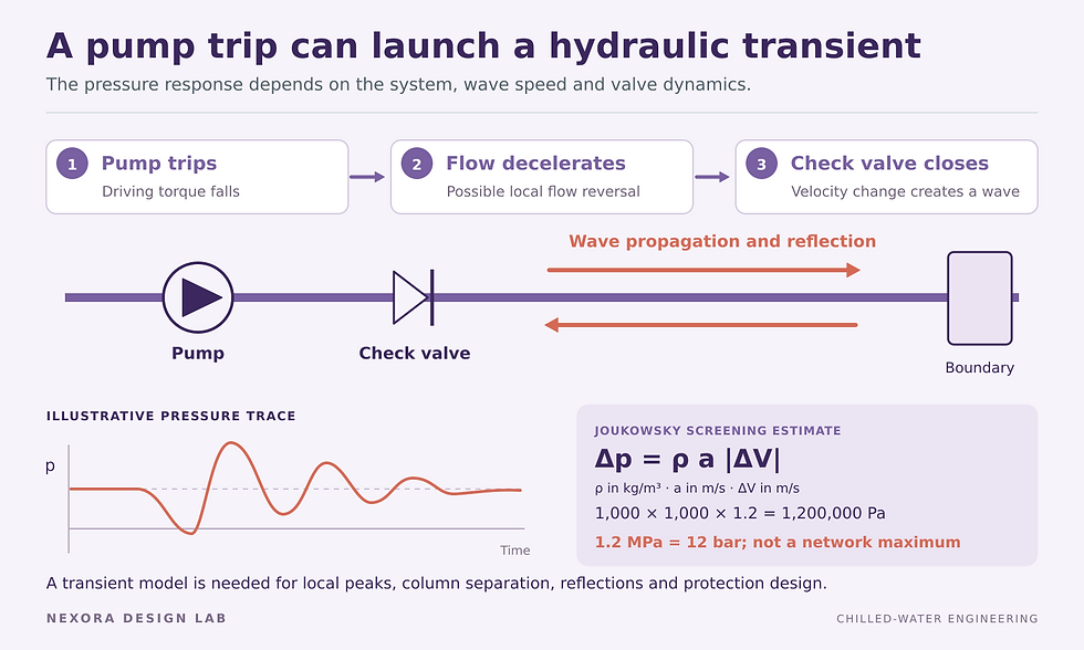
Conceptual pressure response and an illustrative Joukowsky estimate. The 12 bar estimate is not a prediction of the network maximum and does not replace transient analysis.
Check-valve closure needs a dynamic specification
A check valve that allows substantial reverse velocity to develop can create a sharp surge when it finally stops that flow. Selecting it by connection size and steady pressure loss leaves this behaviour unspecified. Request dynamic information relating flow deceleration to reverse velocity at closure, for the proposed size, orientation and spring or damping arrangement.
Val-Matic's Dynamic Characteristics of Check Valves explains why valve behaviour must be matched to the pumping system. Short travel, low moving inertia and suitable spring assistance can help a valve close before appreciable reverse flow develops. A controlled slow-closing arrangement uses a different strategy and must accommodate the resulting reverse flow and possible pump backspin.
Example 2: why reverse velocity matters
For illustration, suppose two candidate valves in the same model stop reverse velocities of 0.15 m/s and 0.60 m/s. These values are hypothetical inputs, not ratings for particular valve types. With the same water density and wave speed used above:
Candidate A: Δp = 1000 × 1000 × 0.15 = 150,000 Pa = 1.5 bar
Candidate B: Δp = 1000 × 1000 × 0.60 = 600,000 Pa = 6.0 bar
The fourfold difference comes from the velocity arrested at seating. Use the reverse velocity immediately before closure for this local screening calculation, rather than automatically substituting the original forward design velocity. The result still needs to be combined with the preceding pressure history and network reflections in a transient model.
Ask for the origin and applicable range of supplier data. The label “non-slam” does not demonstrate acceptable behaviour in the specified trip cases.
Review the low-pressure envelope as carefully as the peak
Prepare both maximum and minimum pressure envelopes along the network. Convert pressure to absolute units before comparing it with the fluid's vapour pressure. Account for elevation and the actual fill-pressure arrangement; pump differential pressure alone does not give local absolute pressure at a high point.
If a preliminary calculation predicts a pressure below vapour pressure, continuing a single-phase calculation into arbitrarily negative absolute pressure has no physical meaning. Vapour-cavity formation and subsequent collapse need an appropriate model and specialist judgement. Review external-pressure resistance and the consequences of air ingress as well as positive internal pressure.
Check evaporators, coils, flexible connectors, strainers, valves and instruments. Give the structural designer transient loads and time histories at bends, tees and restraints. A pressure test certificate does not establish fatigue performance under repeated dynamic loading.
Build a study that can be checked
The study brief should include pipe lengths, internal diameters, wall properties, elevations, fluid data, pump curves and rotating inertia. Include check-valve dynamics, actuator travel and flow characteristics, control sequences, pressurisation connections and any proposed surge device. Verify units and distinguish motor speed decay from liquid-flow decay.
Require these study outputs:
Initial steady-state flows and pressures, reconciled with the design or measured plant
Event timing and assumptions for each operating and failure case
Maximum and minimum pressures at critical components and high points
Pump speed, reverse flow, check-valve closure and any predicted cavity behaviour
Sensitivity to uncertain wave speed, inertia and valve data
Protection performance with credible equipment or control failures
Choose mitigation from the demonstrated mechanism. Options may include a better-matched check valve, a revised actuator closure law, coordinated pump sequencing or a purpose-designed surge vessel. Verify the whole pressure envelope after each change; reducing one peak can leave another event controlling.
A normal VFD stop ramp should not be credited during loss of electrical supply unless the actual drive and power arrangement can deliver that behaviour. Likewise, a thermal expansion vessel needs a transient assessment before it is credited as surge protection. Its connection, available liquid volume and gas response matter.
Commission with evidence and defined limits
Agree a safe, staged test plan with the equipment suppliers and responsible engineer. Set pressure limits, instrument locations, recording bandwidth and abort criteria before testing. Routine building-management trends may miss a sub-second event; choose transducers and sampling to resolve the modelled timescale.
Start with permitted low-risk transitions and compare traces with predictions. Resolve differences before more severe tests. Record approved valve settings, drive parameters and pump sequences for future maintenance.
Nexora's Chilled Water System Design Handbook is a useful companion for the wider design workflow. The Pump Head Calculator Design Suite supports steady-state hydraulic calculations; transient pressure assessment requires a suitable dynamic model and competent specialist review.


Comments