Waterside Economizers: When Cooling Towers Can Provide Chilled Water

Start with the water temperature the load actually needs
A waterside economizer uses favorable outdoor conditions to remove heat from a chilled-water loop without asking the chiller compressor to do all of the work. In a common arrangement, a plate heat exchanger transfers building heat to cooling-tower water while keeping the two water circuits separate.
The deciding question is whether the tower and heat exchanger can deliver useful cooling at the required temperatures and load. A dry-bulb reading, summer tower rating or count of local “cold days” cannot answer it.
This article covers an open evaporative tower with an indirect heat exchanger. Dry coolers require a different performance check.
Account for two temperature approaches
For an evaporative cooling tower, define tower approach as leaving tower-water temperature minus the wet-bulb temperature of the air entering the tower. Tower range is the difference between entering and leaving water temperatures. SPX's explanation of range and approach separates these two quantities and illustrates why fan operation changes the attainable water temperature.
The heat exchanger introduces another approach. Here, define it as chilled-water temperature leaving the exchanger minus tower-water temperature entering it. Ignoring pipe heat gain, a first screening relation is:
TCHW,HX,out ≈ Twb + Atower + AHX
All temperatures are in °C and both approaches are temperature differences in K. Use approaches corresponding to the intended load, flows and equipment operation; a summer tower approach should not be carried unchanged into every winter calculation.
For full economizing, this estimated outlet must be at or below the required chilled-water supply temperature, and the available heat-transfer capacity must meet the entire load. For partial economizing, the outlet only has to be sufficiently below return-water temperature to provide useful precooling, subject to a favorable plant-energy comparison.
Worked example 1: full cooling versus useful precooling
Assume a building needs 400 kW of cooling with 12°C return water and a 7°C supply requirement. For preliminary screening, assume 3°C entering-air wet bulb, a 4 K tower approach and a 2 K exchanger approach at the proposed operating condition. These approaches are illustrative assumptions requiring manufacturer verification.
Leaving tower water = 3 + 4 = 7°C
Estimated chilled water leaving exchanger = 7 + 2 = 9°C
The economizer cannot supply 7°C water by itself under these assumptions. However, a series arrangement could precool the 12°C return to 9°C, leaving the chiller to complete the temperature reduction.
Using water density 1,000 kg/m³, specific heat 4.18 kJ/(kg·K) and negligible heat gains, the building flow is:
V̇ = 400 ÷ (1,000 × 4.18 × 5) = 0.01914 m³/s = 19.14 L/s
At unchanged flow, the illustrative cooling split is:
Economizer duty = 1,000 × 0.01914 × 4.18 × (12 − 9) ≈ 240 kW
Chiller duty = 1,000 × 0.01914 × 4.18 × (9 − 7) ≈ 160 kW
This split is a heat balance, not evidence that the installed exchanger can transfer 240 kW. Its opposite terminal temperature difference, tower-water flow and available surface must also support that duty. The tower must be checked against the total heat rejected through its actual hydraulic arrangement, including condenser heat if it serves the operating chiller.
If the same approaches could be maintained at 1°C wet bulb, the screening outlet would be 1 + 4 + 2 = 7°C. That is a thermal boundary, not a robust enable setpoint. There is no allowance for sensor error, fouling or changing load, and the approaches themselves can change. Obtain actual performance points on both sides of the expected changeover condition.
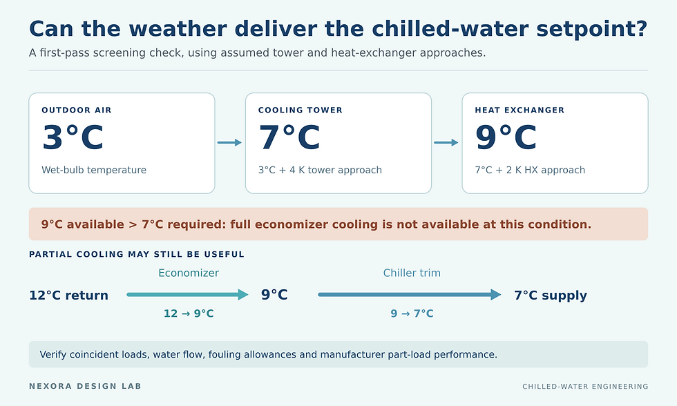
Assumed approaches give 9°C water, so the economizer cannot independently reach a 7°C setpoint. Partial cooling may still be possible; verify actual equipment performance.
Decide how the economizer shares the load
An integrated arrangement allows the economizer and chiller to cool the same return-water stream in sequence. A non-integrated operating scheme changes between economizer-only and mechanical-only cooling. The U.S. Department of Energy's data-center cooling guidance describes an upstream series heat exchanger that can serve as the first cooling stage.
Draw the intended operating modes before finalizing valves. For mechanical-only, full-economizer and integrated operation, mark every active pump, open flow path and temperature-control point. Identify any exchanger or idle evaporator that remains in the circulating path and therefore continues to impose resistance.
For a retrofit, confirm that the proposed circuit can maintain tower flow while meeting the chiller's condenser requirements. Resolve that hydraulic constraint with the equipment suppliers before treating the economizer as a controls-only addition.
Worked example 2: compare total electrical input
A reduction in compressor load is not automatically a reduction in plant electricity. Consider an illustrative 400 kW load at one outdoor condition. Suppose mechanical-only operation draws 72 kW at the chiller, 14 kW at the tower and condenser-water pumps combined, and 10 kW at the chilled-water pumps. Total input is 96 kW.
Now assume a verified integrated operating point draws 36 kW at the chiller, 30 kW at the tower and condenser-water pumps, 8 kW at a dedicated economizer pump, and 12 kW at the chilled-water pumps. Total input is 86 kW.
Net reduction = 96 − 86 = 10 kW
The chiller-input reduction is 36 kW, but the plant reduction is only 10 kW. If the tower and condenser-water combination instead required 42 kW in integrated mode, total input would become 98 kW, exceeding the mechanical-only alternative. These hypothetical comparisons do not predict annual savings.
Trane's waterside economizer engineering guidance emphasizes whole-system energy and coordination with chiller head-pressure control. Use supplier performance data to develop the comparison, then verify the useful changeover region from measured plant power. A remaining chiller load that is too small for stable operation also needs attention.
Turn the selection into a testable sequence
Write an enable condition, a capacity check and an exit condition for each mode. Include a suitable deadband and persistence period so small weather fluctuations do not produce repeated changeovers. Agree on those values during control design.
Require proof of the intended flows and valve positions before releasing a new mode. During a transition, trend supply temperature and define the acceptable excursion and recovery time. Specify the response to failed temperature sensors, unavailable tower cells, a pump failure and an inability to maintain supply temperature. Make the fallback testable.
Give the controls contractor a point list that includes exchanger inlet and outlet temperatures on both sides, representative tower-entering air conditions, relevant flows, plant electrical input and chiller operating status. These points distinguish inadequate tower cooling from inadequate exchanger performance.
Winter operation needs its own design review
Economizer operation can keep an open tower active when a summer-only plant would have shut it down. Review minimum flow per operating cell, water distribution, basin and exposed-pipe protection, inactive equipment and the response to loss of heat load. A satisfactory average basin temperature does not establish that every part of the tower is protected from icing.
SPX's cold-weather operating guidance addresses minimum cell flow, monitoring during freezing conditions, remote sumps, basin heating and exposed piping. Use the selected tower's instructions to develop the winter sequence and operator checks. A basin heater should not be treated as protection for all of the outdoor water circuit.
Evaluate opportunity hour by hour
For feasibility, pair an hourly load profile with local wet-bulb conditions, the required supply temperature and manufacturer tower and exchanger performance. Calculate the feasible operating mode and its total plant power in each relevant bin or hour. Include water treatment, winter operation and maintenance implications in the commercial comparison.
Identify when full economizing is available, when partial economizing is worthwhile, and when mechanical cooling is preferable. The Chilled Water System Design Handbook is a related resource for wider plant coordination. The final design needs verified operating regions and a tested transition sequence.


Comments